Copyright & Fair-use Agreement
UNLV Special Collections provides copies of materials to facilitate private study, scholarship, or research. Material not in the public domain may be used according to fair use of copyrighted materials as defined by copyright law. Please cite us.
Please note that UNLV may not own the copyright to these materials and cannot provide permission to publish or distribute materials when UNLV is not the copyright holder. The user is solely responsible for determining the copyright status of materials and obtaining permission to use material from the copyright holder and for determining whether any permissions relating to any other rights are necessary for the intended use, and for obtaining all required permissions beyond that allowed by fair use.
Read more about our reproduction and use policy.
I agree.Information
Digital ID
Permalink
Details
Member of
More Info
Rights
Digital Provenance
Publisher
Transcription
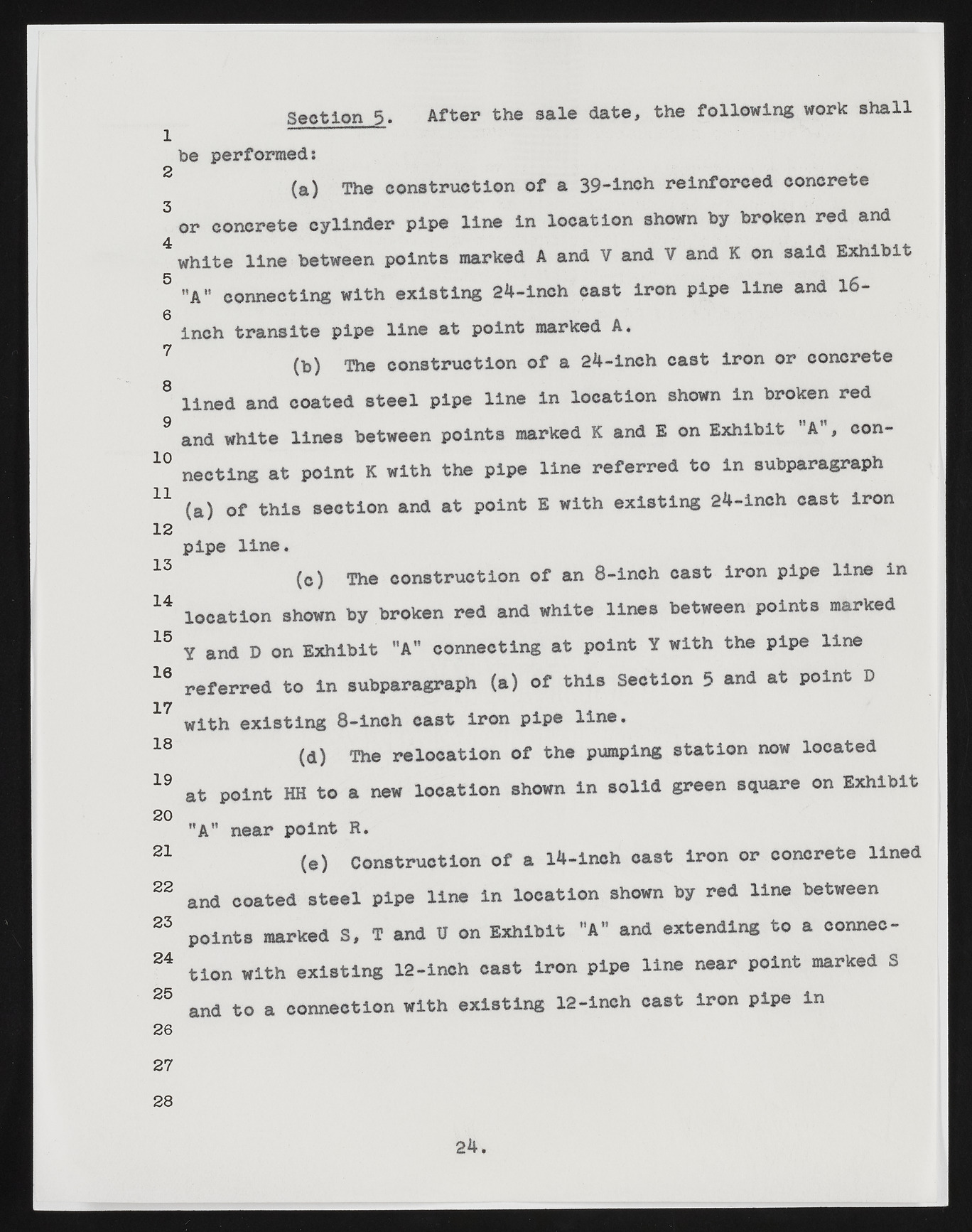
Section 5. After the sale d a t e , the following work shall 1 be performed: (a) The construction of a 39-inch reinforced concrete 3 or concrete cylinder pipe line in location shown by broken red and white line between points marked A and V and V and K on said Exhibit 5 ’'A'* connecting with existing 24-inch cast iron pipe line and 16- 0 inch transite pipe line at point marked A. (b) The construction of a 24-inch cast iron or concrete 8 lined and coated steel pipe line in location shown in broken red and white lines between points marked K and E on Exhibit A , con- 10 necting at point K with the pipe line referred to in subparagraph 11 (a) of this section and at point E with existing 24-inch cast iron 12 pipe line. 13 (c ) The construction of an 8-inch cast iron pipe line in 14 location shown by broken red and white lines between points marked 15 Y and D on Exhibit "A" connecting at point Y with the pipe line 16 referred to in subparagraph (a) of this Section 5 and at point D 17 wit h existing 8-inch cast iron pipe line. 18 (a) The relocation of the pumping station now located 19 at point HH to a new location shown in solid green square on Exhibit 20 "A" near point R. 21 (e ) Construction of a 14-inch cast iron or concrete lined 22 and coated steel pipe line in location shown by red line between 23 points marked S, T and U on Exhibit "A" and extending to a connec- 24 tion with existing 12-lnch cast iron pipe line near point marked S 25 and to a connection with existing 12-inch cast iron pipe in 26 27 28 24.

