Copyright & Fair-use Agreement
UNLV Special Collections provides copies of materials to facilitate private study, scholarship, or research. Material not in the public domain may be used according to fair use of copyrighted materials as defined by copyright law. Please cite us.
Please note that UNLV may not own the copyright to these materials and cannot provide permission to publish or distribute materials when UNLV is not the copyright holder. The user is solely responsible for determining the copyright status of materials and obtaining permission to use material from the copyright holder and for determining whether any permissions relating to any other rights are necessary for the intended use, and for obtaining all required permissions beyond that allowed by fair use.
Read more about our reproduction and use policy.
I agree.Information
Digital ID
Permalink
Details
Member of
More Info
Rights
Digital Provenance
Publisher
Transcription
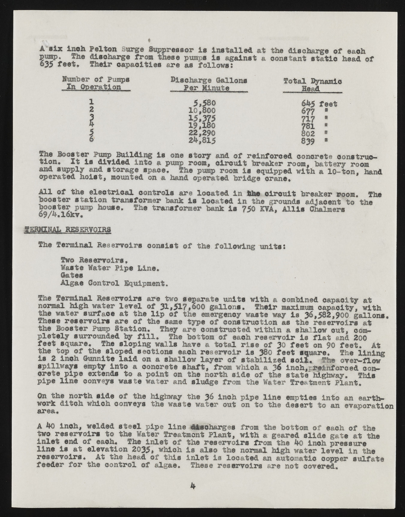
A aXx Inch Peltca Surge Suppressor is Installed at the discharge of eaoh ©map, the dlsoharge from these pumps is against a constant 635 feet, Their capacities are as follows: static head of -lJusmi bOepre roaft Piuomnp s DisPceharr Mgien uGtael lons Totall eaDdynamic 1 5,580 645 feet 2 10,800 677 • 3 15,375 717 t 19,180 781 m | 22,290 802 0 © 24,8*5 839 0 tTihcen *B ooIstt eIrs Pudmipv idBueidl diintnog ais puomnpe rsotoomr,y cainrdc uofi t rebirenafkoerrc erdo ocmo,n cbreattet ercoyn srtoroume-* aonpder sautpepdl hyo iasntd, smtoournatgeed s poanc ea. haTnhde oppuemrpa tredo obmr iisd gee qcuriapnpee.d with a 10-ton, hand All of the electrical controls are located in the circuit breaker room. The bboooosstteerr psutmapt ihoonu ster.a nsTfhoer metrr abnasnfkor imse rl bocanakt eIds i7n5 0t hKeV Ag.r oAulnldsi s adGjhaalcmeenrts to the 69/4.l6kv* TERMINAL RESERVOIRS The Terminal Reservoirs consist of the following units: TWawsot Ree sWeartveori rPsi,pe Line. AGlatgease Control Equipment. The Terminal Reservoirs are two separate units with a combined capacity at ntohre mwaalt ehri gshu wraftaecre laet vetlh e olfi p3 1o,f5 17th,e0 00e mgearlgleonncsy. wasTthee iwra my aixsi m3u6m ,5o8ap2a,9c0l0ty ,g alwliotnh* . These reservoirs are of the same type of construction as the reservoirs at ptlheet eBloyo sstuerrr oPuunmdpe Sdt abtyi ofni.l l. ThTehye arbeo ttcoomn sotfr ucetaecdh wrietsheirnv oiar sihsa lflloawt cuatn,d 2c0o0mftehee t tsoqp uaorfe .t he Tshel opseldo pisencgt wioanlsl s ehaacvhe rae setrotvaoli rr iiss e 38o0f f30e etf eesqtu aorne .9 0 Tfeheet .l inAitn g is 2 inch Sunnite laid on a shallow layer of stabilised sol*. The over—flow csrpeitllew payisp e emexptteyn disn tot o a a cpoonicnrte teo n shtahfet ,n orfrtohm swihdie cohf a t3h6e isntcathe, nhTieglhnwfaoyr.o edT hciosnpipe line conveys waste water and sludge from the Water Treatment Plant. wOonr kth ed intocrh twhh isicdhe coonfv etyhse htihge hwwaasyt et hwea tJ6er i noucth poinp et o litnhee deemspteirets toi naton aenv apeoarratthion area. A 40 inch, welded steel pipe line discharges from the bottom of each of the two reservoir* to the Water Treatment Plant, with a geared slide gate at the inlet end of each. The inlet of the reservoirs from the 4o inch pressure line is at elevation 2035, which is also the normal high water level in the reservoirs. At the head of this inlet is located an automatic copper sulfate feeder for the control of algae. These reservoirs are not covered. k

