Copyright & Fair-use Agreement
UNLV Special Collections provides copies of materials to facilitate private study, scholarship, or research. Material not in the public domain may be used according to fair use of copyrighted materials as defined by copyright law. Please cite us.
Please note that UNLV may not own the copyright to these materials and cannot provide permission to publish or distribute materials when UNLV is not the copyright holder. The user is solely responsible for determining the copyright status of materials and obtaining permission to use material from the copyright holder and for determining whether any permissions relating to any other rights are necessary for the intended use, and for obtaining all required permissions beyond that allowed by fair use.
Read more about our reproduction and use policy.
I agree.Information
Digital ID
Permalink
Details
More Info
Rights
Digital Provenance
Publisher
Transcription
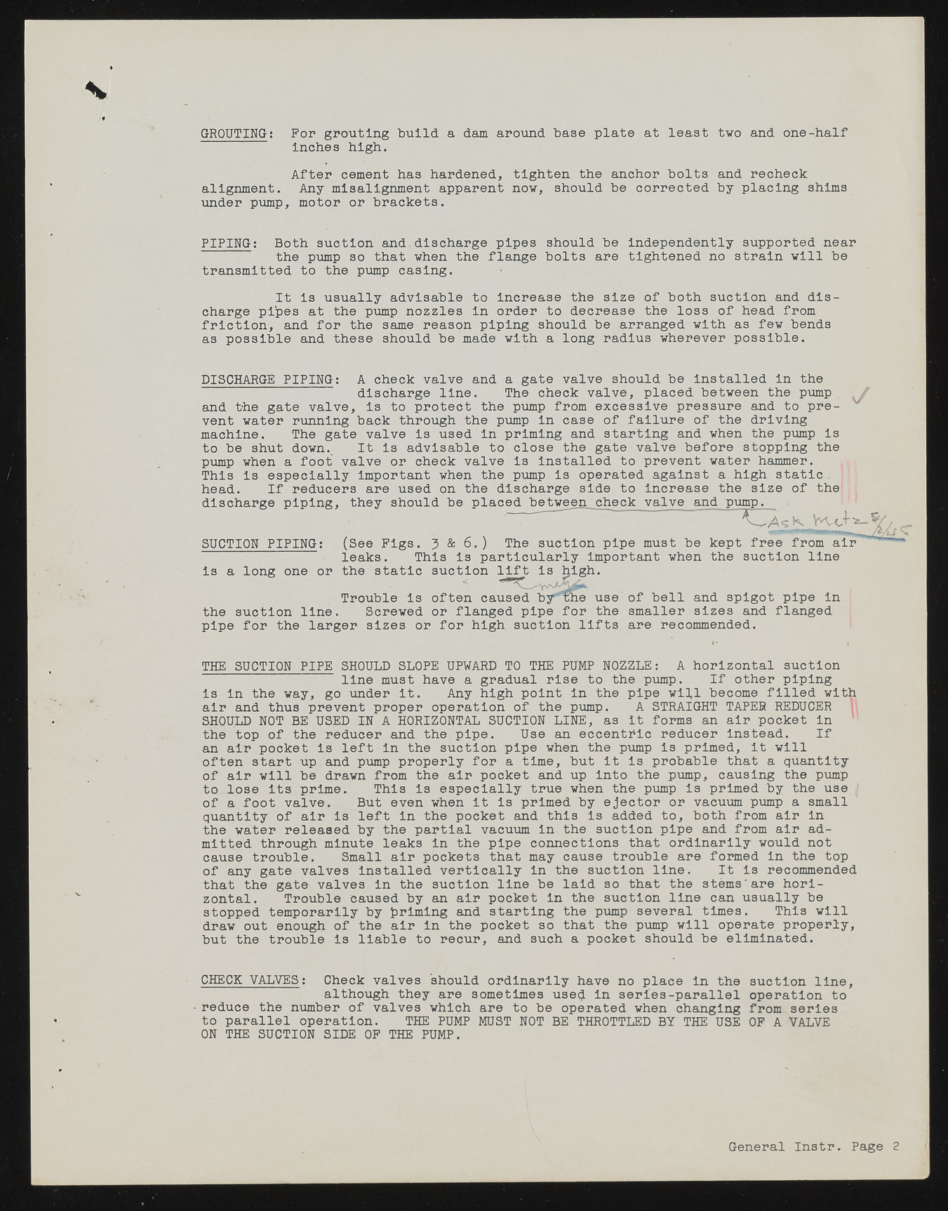
GROUTING: For grouting build a dam around base plate at least two and one-half inches high. After cement has hardened, tighten the anchor bolts and recheck alignment. Any misalignment apparent now, should be corrected by placing shims under pump, motor or brackets. PIPING: Both suction and.discharge pipes should be independently supported near the pump so that when the flange bolts are tightened no strain will be transmitted to the pump casing. charge pipes at the pump nozzles in order to decrease the loss of head from friction, and for the same reason piping should be arranged with as few bends as possible and these should be made with a long radius wherever possible. DISCHARGE PIPING: A check valve and a gate valve should be Installed in the discharge line. The check valve, placed between the pump . , and the gate valve, is to protect the pump from excessive pressure and to prevent water running back through the pump in case of failure of the driving machine. The gate valve is used in priming and starting and when the pump is to be shut down. It is advisable to close the gate valve before stopping the pump when a foot valve or check valve Is installed to prevent water hammer. This is especially important when the pump is operated against a high static. head. If reducers are used on the discharge side to increase the size of the discharge piping, they should be placed between check valve and pump. SUCTION PIPING: (See Figs. j? & 6.) The suction pipe must be kept u - o o xi-um a n - leaks. This is particularly important when the suction line is a long one or the static suction lift is high. the suction line. Screwed or flanged pipe for the smaller sizes and flanged pipe for the larger sizes or for high suction lifts are recommended. THE SUCTION PIPE SHOULD SLOPE UPWARD TO THE PUMP NOZZLE: A horizontal suction line must have a gradual rise to the pump. If other piping is in the way, go under it. Any high point in the pipe will become filled with air and thus prevent proper operation of the pump. A STRAIGHT TAPES REDUCER SHOULD NOT BE USED IN A HORIZONTAL SUCTION LINE, as it forms an air pocket In the top of the reducer and the pipe. Use an eccenthic reducer instead. If an air pocket is left in the suction pipe when the pump is primed, it will often start up and pump properly for a time, but it is probable that a quantity of air will be drawn from the air pocket and up into the pump, causing the pump to lose its prime. This is especially true when the pump Is primed by the use J of a foot valve. But even when It is primed by ejector or vacuum pump a small quantity of air is left in the pocket and this is added to, both from air in the water released by the partial vacuum in the suction pipe and from air admitted through minute leaks in the pipe connections that ordinarily would not cause trouble. Small air pockets that may cause trouble are formed In the top of any gate valves installed vertically in the suction line. It is recommended that the gate valves In the suction line be laid so that the stems'are horizontal. Trouble caused by an air pocket in the suction line can usually be stopped temporarily by griming and starting the pump several times. This will draw out enough of the air In the pocket so that the pump will operate properly, but the trouble is liable to recur, and such a pocket should be eliminated. CHECK VALVES: Check valves should ordinarily have no place in the suction line, although they are sometimes usecj In series-parallel operation to reduce the number of valves which are to be operated when changing from series to parallel operation. THE PUMP MUST NOT BE THROTTLED BY THE USE OF A VALVE ON THE SUCTION SIDE OF THE PUMP. It is usually advisable to increase the size of both suction and dis- Trouble Is often caused by*The use of bell and spigot pipe in General Instr. Page 2

