Copyright & Fair-use Agreement
UNLV Special Collections provides copies of materials to facilitate private study, scholarship, or research. Material not in the public domain may be used according to fair use of copyrighted materials as defined by copyright law. Please cite us.
Please note that UNLV may not own the copyright to these materials and cannot provide permission to publish or distribute materials when UNLV is not the copyright holder. The user is solely responsible for determining the copyright status of materials and obtaining permission to use material from the copyright holder and for determining whether any permissions relating to any other rights are necessary for the intended use, and for obtaining all required permissions beyond that allowed by fair use.
Read more about our reproduction and use policy.
I agree.Information
Digital ID
Permalink
Details
More Info
Rights
Digital Provenance
Publisher
Transcription
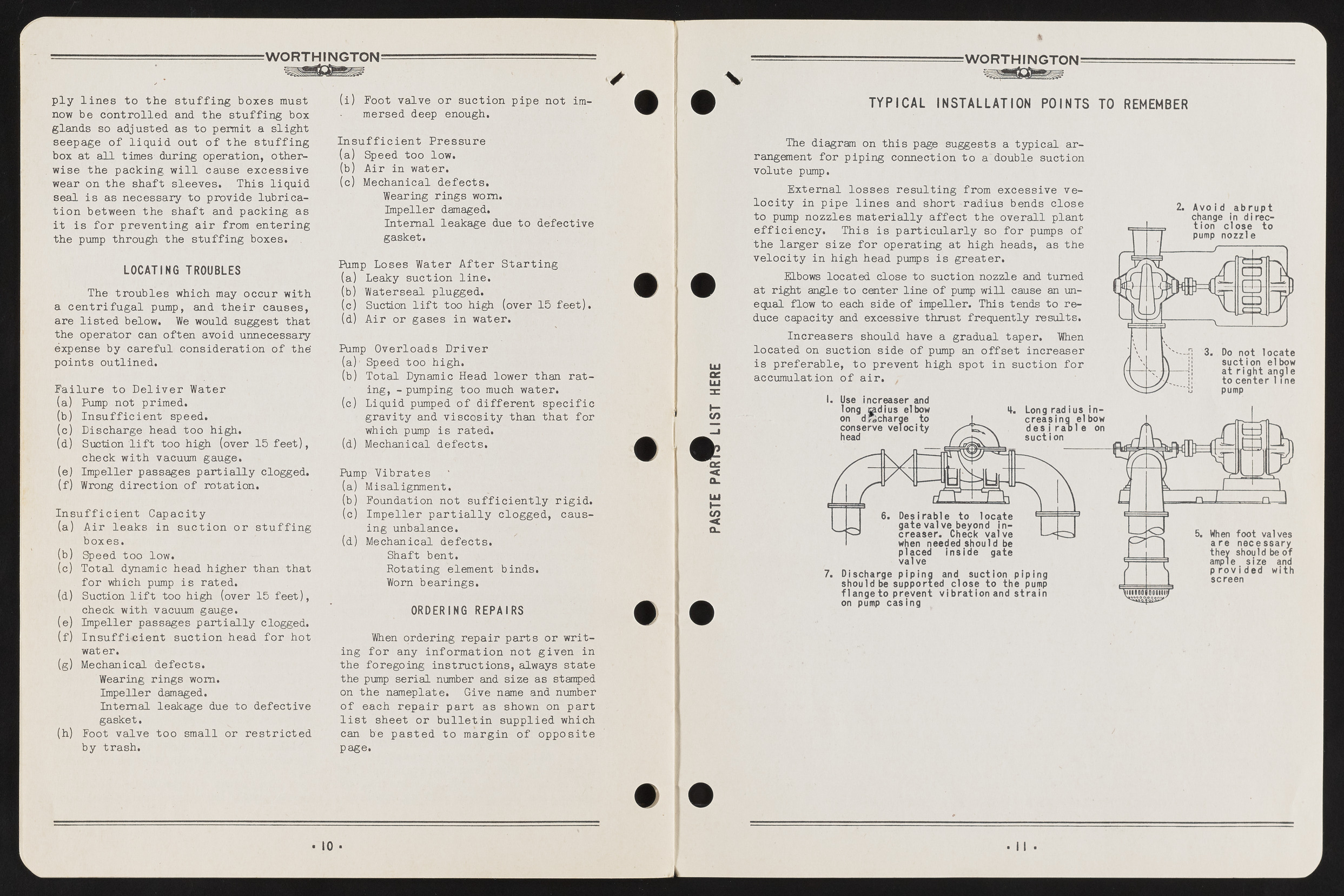
W O R TH IN G TO N ply lines to the stuffing boxes must now be controlled and the stuffing box glands so adjusted as to permit a slight seepage of liquid out of the stuffing box at all times during operation, otherwise the packing will cause excessive wear on the shaft sleeves. This liquid seal is as necessary to provide lubrication between the shaft and packing as it is for preventing air from entering the pump through the stuffing boxes. (i) Foot valve or suction pipe not immersed deep enough. Insufficient Pressure (a) Speed too low. (b) Air in water. (c) Mechanical defects. Wearing rings worn, impeller damaged. Internal leakage due to defective gasket. ? LOCATING TROUBLES The troubles which may occur with a centrifugal pump, and their causes, are listed below. We would suggest that the operator can often avoid unnecessary expense by careful consideration of the' points outlined. Failure to Deliver Water (a) Pump not primed. (b) Insufficient speed. (c) Discharge head too high. (d) Suction lift too high (over 15 feet), check with vacuum gauge. (e) Impeller passages partially clogged. (f) Wrong direction of rotation. Insufficient Capacity (a) Air leaks in suction or stuffing boxes. (b) Speed t oo low. (c) Total dynamic head higher than that for which pump is rated. (d) Suction lift too high (over 15 feet), check with vacuum gauge. (e) Impeller passages partially clogged. (f) Insufficient suction head for hot water. (g) Mechanical defects. Wearing rings worn. Impeller damaged. Internal leakage due to defective gasket. (h) Foot valve too small or restricted by trash. Pump Loses Water After Starting (a) Leaky suction line. (b) Waterseal plugged. (c) Suction lift too high (over 15 feet). (d) Air or gases in water. Pump Overloads Driver (a) ' Speed too high. (b) Total Dynamic Head lower than rating, - pumping too much water. (c) Liquid pumped of different specific gravity and viscosity than that for which pump is rated. (d) Mechanical defects. Pump Vibrates (a) Misalignment. (b) Foundation not sufficiently rigid. (c) Impeller partially clogged, causing unbalance. (d) Mechanical defects. Shaft bent. Rotating element binds. Worn bearings. ORDERING REPAIRS When ordering repair parts or writing for any information not given in the foregoing instructions, always state the pump serial number and size as stamped on the nameplate. Give name and number of each repair part as shown on part list sheet or bulletin supplied which can be pasted to margin of opposite page. 10 PASTE P A R IS H ST HERE V W O R TH IN G TO N TYPICAL INSTALLATION POINTS TO REMEMBER The diagram on this page suggests a typical arrangement for piping connection to a double suction volute pump. External losses resulting from excessive velocity in pipe lines and short radius bends close to pump nozzles materially affect the overall plant efficiency. This is particularly so for pumps of the larger size for operating at high heads, as the velocity in high head pumps is greater. Elbows located close to suction nozzle and turned at right angle to center line of pump will cause an unequal flow to each side of impeller. This tends to reduce capacity and excessive thrust frequently results. Increasers should have a gradual taper. When located on suction side of pump an offset increaser is preferable, to prevent high spot in suction for accumulation of air. 1 Use increaser and long cadi us elbow on d^charge to conserve velocity head 4. Long rad ius increasing elbow d e s i ra o l e on suction Desirable to locate gate valve beyond increaser. Check valve when needed should be D l a c e d i n s i d e d a t e 7. Discharge piping and suction piping should be supported close to the pump flange to prevent v ib ra tio n and s tra in on pump casing Avoi d a b r u p t change in directio n close to pump nozzle / L “T J J k Jj Do not locate suction elbow at rig h t angle to center 1 1 ne pump When foot valves a re necessary they should be of ample size and p r o v i d e d with screen

