Copyright & Fair-use Agreement
UNLV Special Collections provides copies of materials to facilitate private study, scholarship, or research. Material not in the public domain may be used according to fair use of copyrighted materials as defined by copyright law. Please cite us.
Please note that UNLV may not own the copyright to these materials and cannot provide permission to publish or distribute materials when UNLV is not the copyright holder. The user is solely responsible for determining the copyright status of materials and obtaining permission to use material from the copyright holder and for determining whether any permissions relating to any other rights are necessary for the intended use, and for obtaining all required permissions beyond that allowed by fair use.
Read more about our reproduction and use policy.
I agree.Information
Digital ID
Permalink
Details
More Info
Rights
Digital Provenance
Publisher
Transcription
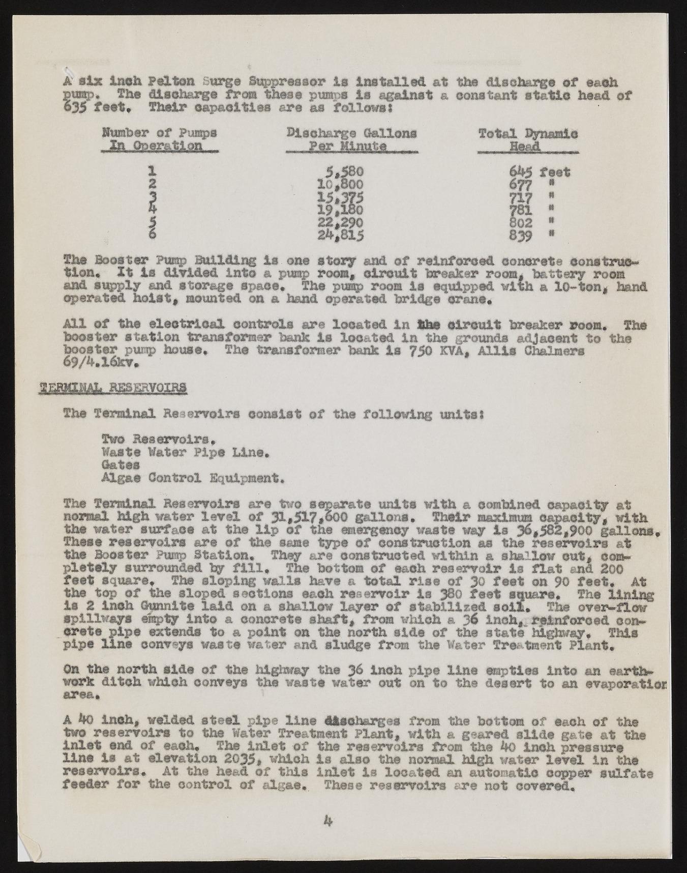
A six inch Felton surge Suppressor Is installed at the discharge of eaoh pwsp. ?he discharge frees these pumps Is against a constant static head of ©35 feet* Their capacities are as follows} lumber of Pumps la Operation Discharge Gallons Per Minute.. Total Dynamic Head 1 2 Bk 6b5 feet 677 * i im 717 * 781 “ 22,290 §02 ? i 2b,815 839 « The Booster Pump Building is one story and of reinforced concrete construction* It is divided into a pump room, circuit breaker room, battery room and supply and storage space* The pump room is equipped with a 10-ton, hand operated hoist, mounted on a hand aerated bridge crane* All of the electrical controls are located in the circuit breaker room. The booster station transformer bank is located in the grounds adjacent to the booster pump house* The transformer bank la 750 KVA, Mils Chalmers 69/b,X6kv* The Terminal Reservoirs consist of the following units! Two Reservoirs, Waste Water Pipe Line* Gates Algae Control Equipment, The Terminal Reservoirs are two separate units with a combined capacity at normal high water level of 31,517,600 gallons. Their maximum capacity, with the water surface at the lip of the emergency waste way is 36,582,900 gallons* These reservoirs are of the same type of construction as the reservoirs at the Booster Pump Station. They are constructed within a shallow out, completely surrounded by fill. The bottom of each reservoir is flat and 200 feet square. The sloping walls have a total rise of 30 feet on 90 feet* At the top of the sloped sections each reservoir is 380 feet square* The lining is 2 inch Granite laid on a shallow layer of stabilised soil* The over-flow spillways empty into a concrete shaft, from which a % inch,^ reinforced concrete pipe extends to a point on the north side of the state highway. This pipe line conveys waste water and sludge from the Water Treatment Plant* On the north side of the highway the 36 inch pipe line empties into an earthwork ditch which conveys the waste water out on to the desert to an evaporation area* A bo Inch, welded steel pipe line discharges from the bottom of eaoh of the two reservoirs to the Water Treatment Plant, with a geared slide gate at the inlet end of each* The inlet of the reservoirs from the bo inch pressure line is at elevation 2035# which is also the normal high water level in the reservoirs* At the head of this inlet is located an automatic copper sulfate feeder for the control of algae*. These reservoirs are not covered.

