Copyright & Fair-use Agreement
UNLV Special Collections provides copies of materials to facilitate private study, scholarship, or research. Material not in the public domain may be used according to fair use of copyrighted materials as defined by copyright law. Please cite us.
Please note that UNLV may not own the copyright to these materials and cannot provide permission to publish or distribute materials when UNLV is not the copyright holder. The user is solely responsible for determining the copyright status of materials and obtaining permission to use material from the copyright holder and for determining whether any permissions relating to any other rights are necessary for the intended use, and for obtaining all required permissions beyond that allowed by fair use.
Read more about our reproduction and use policy.
I agree.Information
Digital ID
Permalink
Details
Member of
More Info
Rights
Digital Provenance
Publisher
Transcription
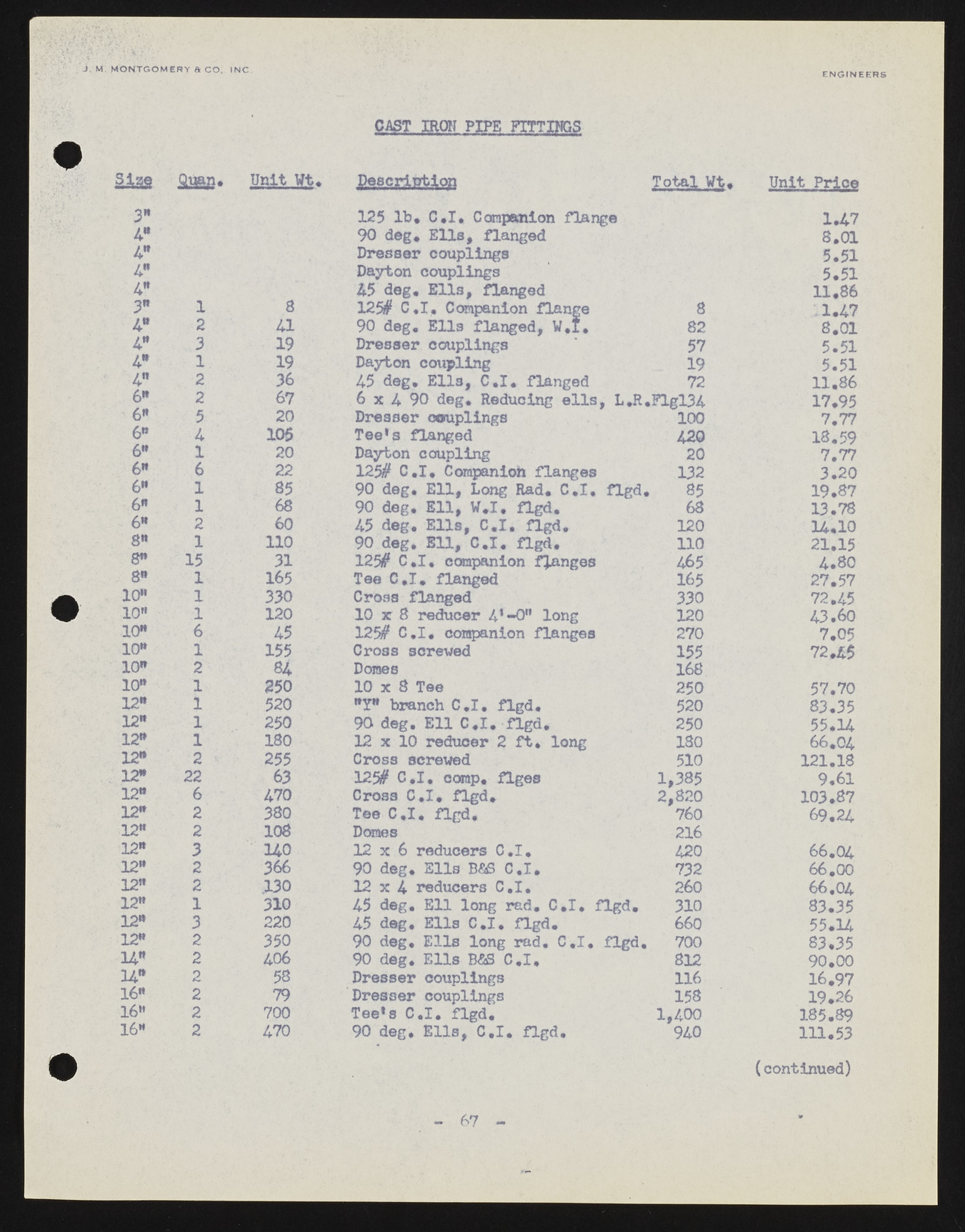
J . M M O N T G O M E R Y a C O , IN C . FE wN G. IINN1E, Er DR CS CAST IRON PIPE FITTIHGS Size Quap. Unit Wt. Description Total Wt. Unit Prioe 3" 125 lb* C.X. Companion flange 1.47 4* 90 deg* Elies, flanged 8.01 4" Dresser couplings 5.51 A* Dayton couplings 5.51 A9 45 deg. Ells, flanged 11,86 3" 1 8 125# C.I, Companion flange 8 •1.47 A * 2 a 90 deg. E n s flanged, W,I. 82 8.01 A9 3 19 Dresser couplings 57 5.51 A9 1 19 Dayton coupling 19 5.51 A " 2 36 45 deg* Ells, C.I* flanged 72 11.86 6® 2 67 6 x 4 90 deg. Reducing ells , 1>«R«,Flgl34 17.95 6* 5 20 Dresser couplings 100 7.77 6" A 106 Tee's flanged 420 18.59 6" 1 20 Dayton coupling 20 7.77 6" 6 22 125# C.I, Companion flanges 132 3.20 6** 1 85 90 deg* Ell, Long Rad* C.I* flgd. 85 19.87 6" 1 68 90 deg. E n , W.I. flgd. 68 13.78 6" 2 60 45 deg. Ells, C*I* flgd. 120 14.10 8" 1 110 90 deg. E U , C.I. flgd. n o 21.15 8" 15 31 125# C.I. companion flanges 465 4.80 8" 1 165 Tee C.I. flanged 165 27.57 10" 1 330 Cross flanged 330 72.45 10" 1 120 10 r 8 reducer 4'-0" long 120 43.60 10" 6 A5 125# C.I. companion flanges 270 7.05 10" 1 155 Cross screwed 155 72,45 10" 2 84 Domes 168 10" 1 250 10 x 8 Tee 250 57.70 12* 1 520 *Y" branch C.I. flgd. 520 83.35 12" 1 250 90 deg. Ell C.I. flgd. 250 55.14 12" 1 180 12 x 10 reducer 2 ft, long 180 66,04 12* 2 255 Cross screwed 510 121.18 12" 22 63 125# C.I. comp, flges 1,385 9.61 12" 6 470 Cross C.I. flgd. 2,820 103.87 12" 2 380 Tee C.I. flgd. 760 69.24 12" 2 108 Domes 216 12" 3 140 12 x 6 reducers C.I. 420 66.04 12" 2 366 90 deg. Ells B&S C.I. 732 66.00 12" 2 330 12 x 4 reducers C.I. 260 66.04 12" 1 310 45 deg. Ell long rad. C.I. flgd. 310 83.35 12" 3 220 45 deg. Ells C.I. flgd. 660 55.14 12" 2 350 90 deg. Ells long rad. C.I. flgd. 700 83.35 1A” 2 406 90 deg. Ells BfiS C.I, 812 90.00 14* 2 58 Dresser couplings 116 16.97 16* 2 79 Dresser couplings 158 19.26 16" 2 700 Tee's C.I. flgd. 1,400 185.89 16" 2 470 90 deg. Ells, C.I. flgd. 940 111.53 (continued) 67

