Copyright & Fair-use Agreement
UNLV Special Collections provides copies of materials to facilitate private study, scholarship, or research. Material not in the public domain may be used according to fair use of copyrighted materials as defined by copyright law. Please cite us.
Please note that UNLV may not own the copyright to these materials and cannot provide permission to publish or distribute materials when UNLV is not the copyright holder. The user is solely responsible for determining the copyright status of materials and obtaining permission to use material from the copyright holder and for determining whether any permissions relating to any other rights are necessary for the intended use, and for obtaining all required permissions beyond that allowed by fair use.
Read more about our reproduction and use policy.
I agree.Information
Digital ID
Permalink
Details
More Info
Rights
Digital Provenance
Publisher
Transcription
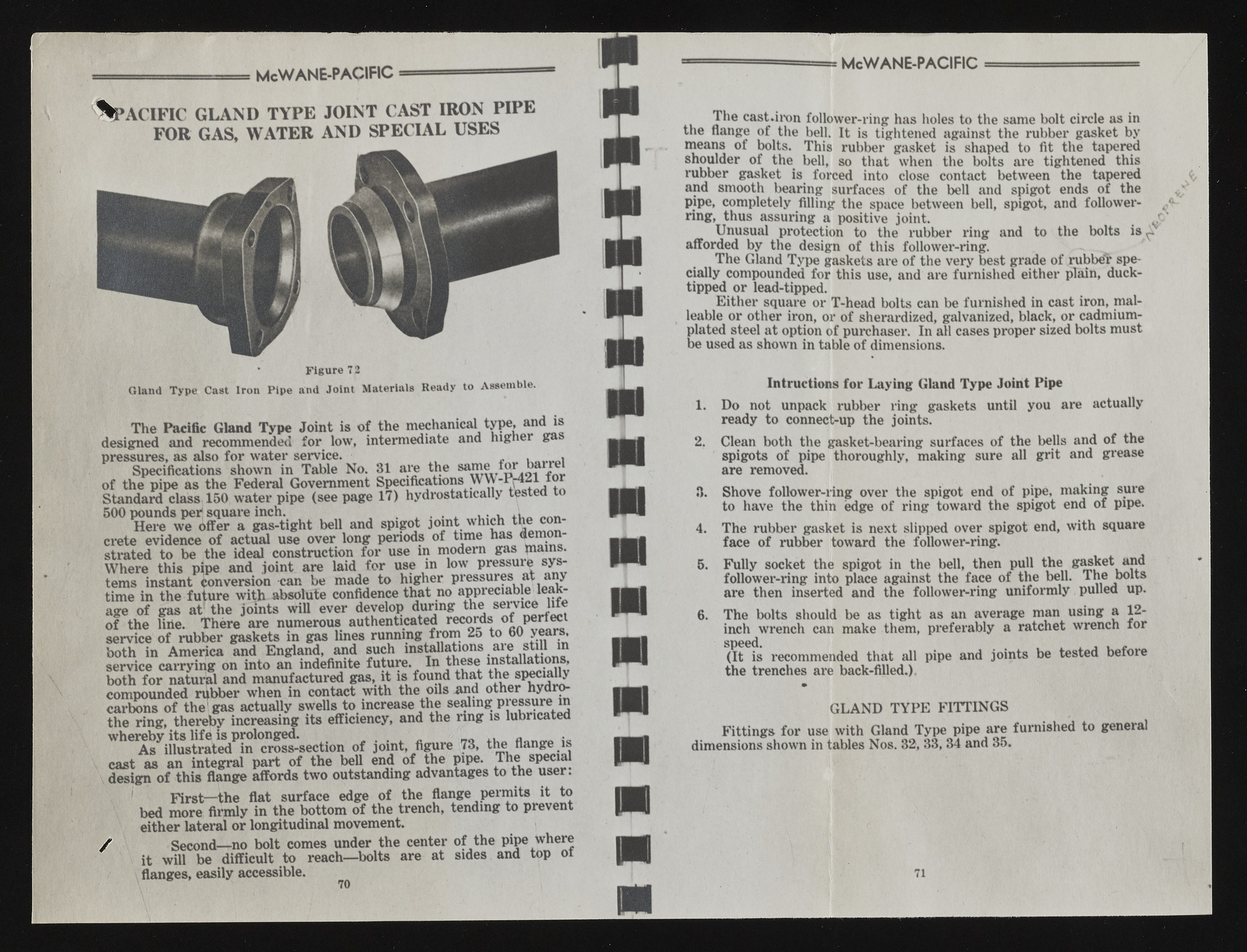
....... M cW ANE-PACIFIC — P a c i f i c g l a n d t y p e j o i n t c a s t i r o n p i p e FOR GAS, W A T E R A N D SPECIAL USES * Figure 7 2 Gland Type Cast Iron Pipe and Joint Materials Ready to Assemble. The Pacific Gland Type Joint is o f the mechanical type, and is designed and recommended for low, intermediate and higher ga pressures, as also for water service. , „ . Specifications shown in Table No. 31 are the same' fW’ bj of the pipe as the Federal Government Specifications W W -IM 2 lio r Standard class 150 water pipe (see page 17) hydrostatically tested t 500 pounds per1 square inch. . , , . . , . . . A Here we offer a gas-tight bell and spigot joint which the concrete evidence o f actual use over long periods of time has demonstrated to be the ideal construction for use in modem gas plains. Where this pipe and joint are laid for use in low pressure systems instant Conversion can be made to higher pressures at any time in the future with absolute confidence that no appreciable leakage of gas at1 the joints will ever develop during the service lite o f the line. There are numerous authenticated records °* service of rubber gaskets in gas lines running from 25 to 60 years, both in America and England, and such installations are stul in service carrying on into an indefinite future. In these installations, both for natural and manufactured gas, it is found that the specially compounded rubber when in contact with the oils and other hydrocarbons o f the'gas actually swells to increase the sealing pressure in the ring, thereby increasing its efficiency, and the ring is lubricated whereby its life is prolonged. . __ ,, • As illustrated in cross-section of joint, figure 73, the flange is cast as an integral part of the bell end of the pipe. ^Die sp«aal design o f this flange affords two outstanding advantages to the user. First—the flat surface edge of the flange permits it to bed more firmly in the bottom o f the trench, tending to prevent either lateral or longitudinal movement. / I Second— no bolt comes under the center of the pipe where it will be difficult to reach— bolts are at sides and top oi flanges, easily accessible. 70 McWANE-PACIFIC T h e cast.iron follower-ring has holes to the same bolt circle as in the flange of the bell. It is tightened against the rubber gasket by means of bolts. Th is rubber gasket is shaped to fit the tapered shoulder of the bell, so that when the bolts are tightened this rubber gasket is forced into close contact between the tapered and smooth bearing surfaces of the bell and spigot ends of the pipe, completely filling the space between bell, spigot, and followerring, thus assuring a positive joint. J Unusual protection to the rubber ring and to the bolts is ^ afforded by the design of this follower-ring. T h e Gland Typ e gaskets are of the very best grade of rabbet specially compounded for this use, and are furnished either plain, duck-tipped or lead-tipped. Eith e r square or T-head bolts can be furnished in cast iron, malleable or other iron, or of sherardized, galvanized, black, or cadmium-plated steel at option of purchaser. In all cases proper sized bolts must be used as shown in table of dimensions. Infractions for Laying Gland Type Joint Pipe 1. Do not unpack rubber ring gaskets until you are actually ready to connect-up the joints. 2. Clean both the gasket-bearing surfaces of the bells and of the spigots of pipe thoroughly, making sure all grit and grease are removed. 8. Shove follower-ring over the spigot end of pipe, making sure to have the thin edge of ring toward the spigot end of pipe. 4. The rubber gasket is next slipped over spigot end, with square face of rubber toward the follower-ring. 5. Fully socket the spigot in the bell, then pull the gasket and follower-ring into place against the face of the bell. The bolts are then inserted and the follower-ring uniformly pulled up. 6. The bolts should be as tight as an average man using a 12- inch wrench can make them, preferably a ratchet wrench for S(pI6t6 Qiis recommended that all pipe and joints be tested before the trenches are back-filled.). GLAND TYPE FITTINGS Fittings for use with Gland Type pipe are furnished to general dimensions shown in tables Nos. 32, 33, 34 and 35. 71

