Copyright & Fair-use Agreement
UNLV Special Collections provides copies of materials to facilitate private study, scholarship, or research. Material not in the public domain may be used according to fair use of copyrighted materials as defined by copyright law. Please cite us.
Please note that UNLV may not own the copyright to these materials and cannot provide permission to publish or distribute materials when UNLV is not the copyright holder. The user is solely responsible for determining the copyright status of materials and obtaining permission to use material from the copyright holder and for determining whether any permissions relating to any other rights are necessary for the intended use, and for obtaining all required permissions beyond that allowed by fair use.
Read more about our reproduction and use policy.
I agree.Information
Digital ID
Permalink
Details
More Info
Rights
Digital Provenance
Publisher
Transcription
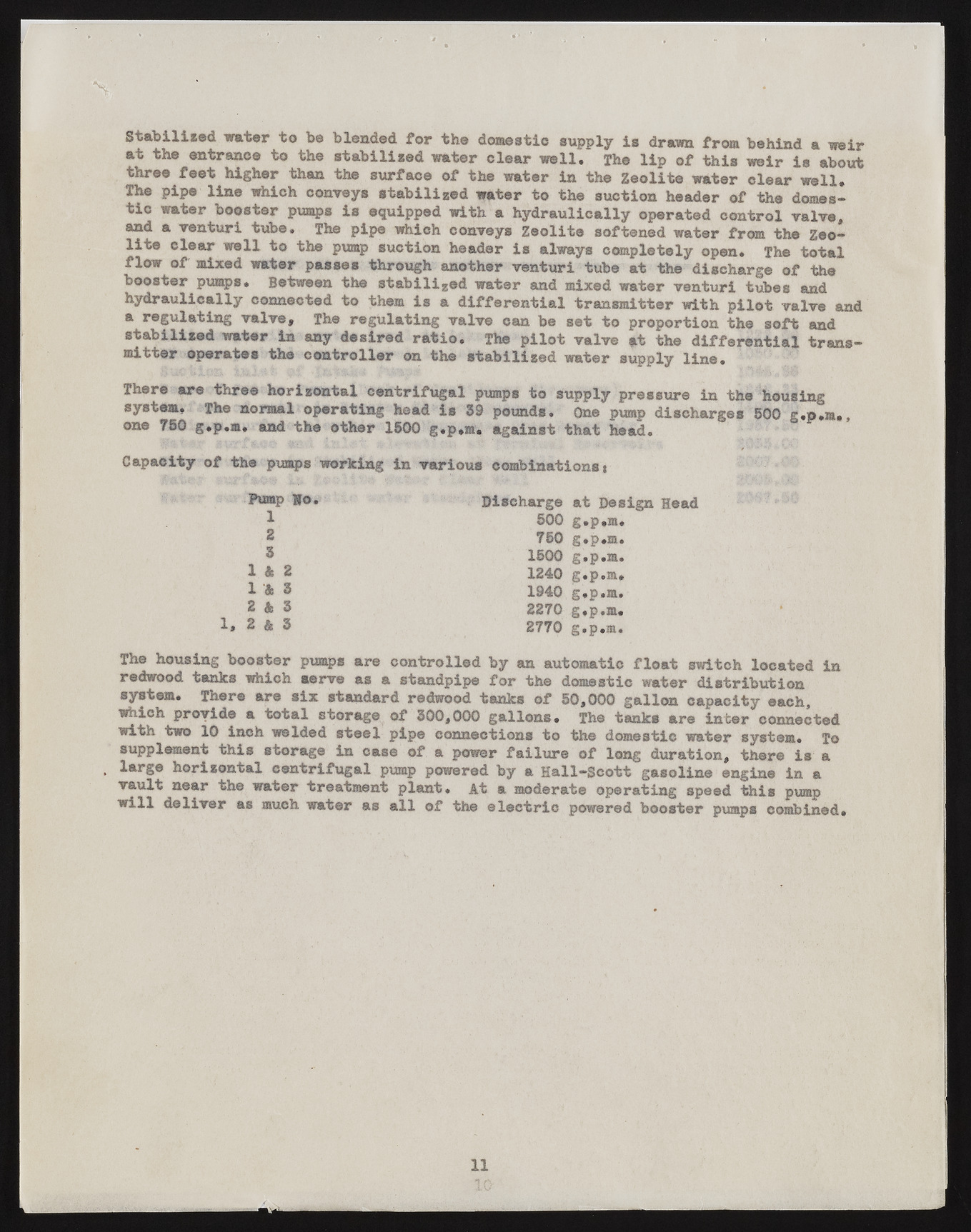
n Stabilised water to be blended for the domestic supply is drawn from behind a weir at the entrance to the stabilised water clear well. The lip of this weir is about three feet higher than the surface of the water in the Zeolite water clear well. The pipe line which conveys stabilized water to the suction header of the domestic water booster pumps is equipped with a hydraulically operated control valve, and a venturi tube. The pipe which conveys Zeolite softened water from the Zeolite clear well to the pump suction header is always completely open. The total flow of mixed water passes through another venturi tube at the discharge of the booster pumps. Between the stabilised water and mixed water venturi tubes and hydraulically connected to them is a differential transmitter with pilot valve a regulating valve. The regulating valve can be set to proportion the soft and stabilized water in any desired ratio. The pilot valve at the differential transmitter operates the controller on the stabilized water supply line. There are three horizontal centrifugal pumps to supply pressure in the housing system. The normal operating head is 39 pounds. One pump discharges 500 g.p.m*, one 750 g.p.m. and the other 1500 g.p.m. against that head. Capacity of the pumps working in various combinations * Pump Ho. Discharge at Des: 1 500 g.p.m. 2 750 g.p.m. 5 1500 g.p.m. 1 & 2 1240 g.p.m. X k 8 1940 g.p.m. 2 A 3 2270 g.p.m. 2 & 3 2770 g.p.m. The housing booster pumps are controlled by an automatic float switch located in redwood tanks which serve as a standpipe for the domestic water distribution system. There are six standard redwood tanks of 50,000 gallon capacity each, which provide a total storage of 300,000 gallons. The tanks are inter connected with two 10 inch welded steel pipe connections to the domestic water system. To supplement this storage in case of a power failure of long duration, there is a , large horizontal centrifugal pump powered by a Hall—Scott gasoline engine in a vault near the water treatment plant* At a moderate operating speed this pump will deliver as much water as all of the electric powered booster pumps combined. 11

