Copyright & Fair-use Agreement
UNLV Special Collections provides copies of materials to facilitate private study, scholarship, or research. Material not in the public domain may be used according to fair use of copyrighted materials as defined by copyright law. Please cite us.
Please note that UNLV may not own the copyright to these materials and cannot provide permission to publish or distribute materials when UNLV is not the copyright holder. The user is solely responsible for determining the copyright status of materials and obtaining permission to use material from the copyright holder and for determining whether any permissions relating to any other rights are necessary for the intended use, and for obtaining all required permissions beyond that allowed by fair use.
Read more about our reproduction and use policy.
I agree.Information
Digital ID
Permalink
Details
Member of
More Info
Rights
Digital Provenance
Publisher
Transcription
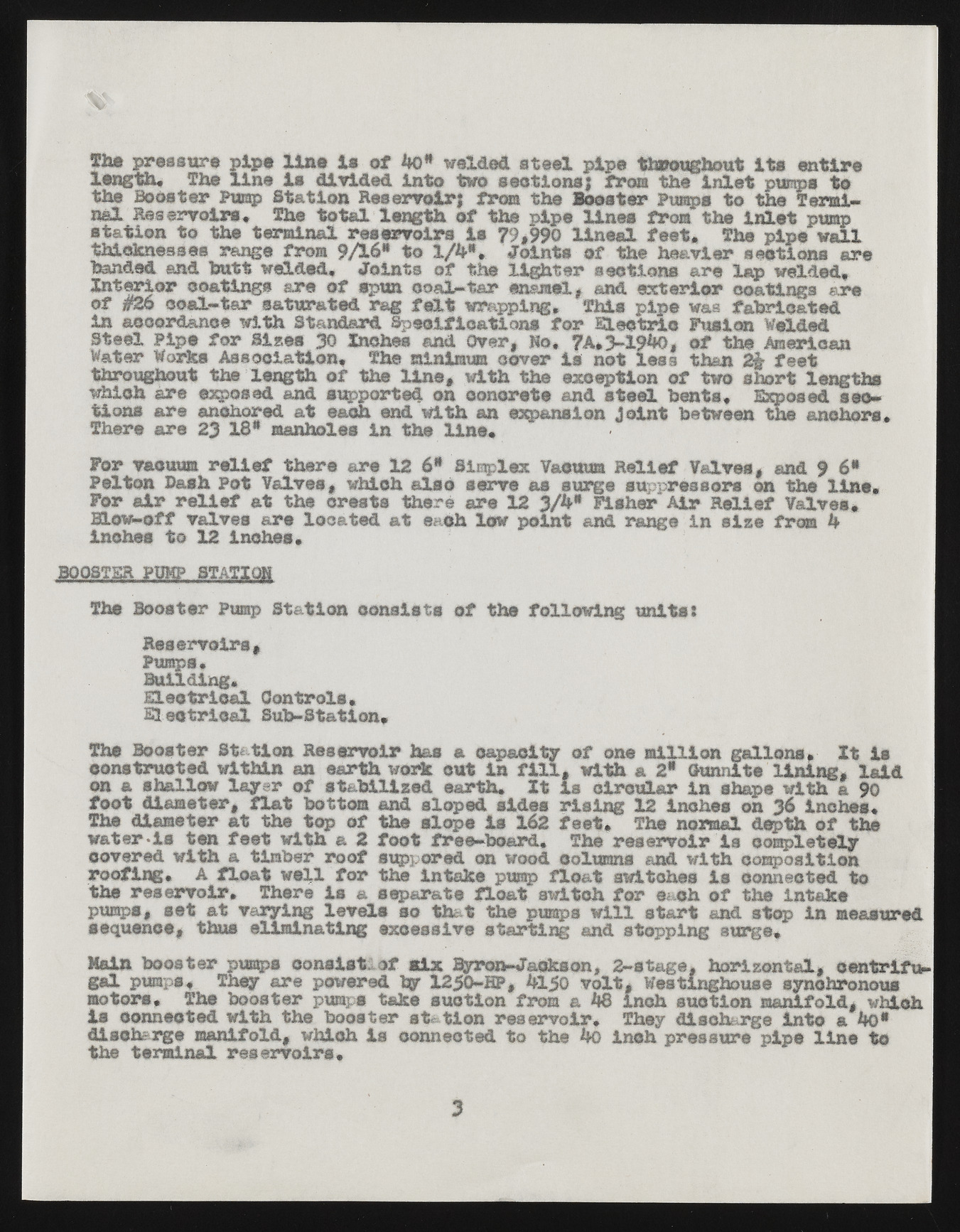
Jb* pressure pipe line la of 40* welded steal length. The line la divided Into two sections}p ifpreo stth rtohue gIhnoluett i ptsu mpesn ttiore the Booster Pump Station Reservoir} from the Booster Pumps to the Termisntaalt Rieosne rtvoo itrhse* teTrhmein atlo traels leervnogitrhs oifs t7he9 ,9p9i0p el linineeasl ffereotm* thTeh Ien pliepte p wuamlpl thicknesses range from 9/16* to 1/4*. Joints of the heavier sections ar e handed and butt welded* Joints of the lighter sections are lap welded* Interior coatings are of spun coal-tar enamelt and exterior coatings ar e of #26 coal-tar saturated rag fdt wrapping. This pipe was fabricated ISnt eaeclc Poirpdaen fcoe rw iSltrh. eSs ta30n dIanrcdh eSsp eacnifdi coavteri,o nsho .f o7rA *E l3-e1c9t*rKi>,c Foufs itohne AWmeelrdiecda n Water Works Association, The minimum cover is not less than 2$- feet throughout the length of the line* with the exception of two short le ngths wthiioncsh aarree aenxcphoosreedd a nadt eeaxcpho retnedd w oint hc aonnc reextpea nasnidon s Jtoeieln tb ebnettsw*e enE xthpeo saendc hsoercs* There are 23 18* manholes in the line* For vacuum relief there are 12 6* Simplex Vacuum Relief Valves, and 9 6* PFeolr taoinr b raeslhi Peoft a tVa ltvhees ,c rwehstisc ht ahlesroe asreer v1e2 a s3 /4s*u rgFeis hseurp pAriesrs oRresl ieofn Vtahlev elsi*ne* Blow-off valves are located at each low point and range in size frees 4 inches to 12 inches* BOOSTER PUMP STATIOH The Booster Pump Station consists of the following units: RPeumspesr*voirs, Building. EElleeccttrriiccaall CSuobn-tSrtoaltsi.on* Tchosn stBroousctteerd wSittahtiino na Rne seearrvtohi wro hraks caut cianpa fciiltly, owfi tonhe a m i2l* lOiuonnn lgatlel olnisn*i ng,I tl aisi d on a shallow layer of stabilized earth. It is circular in shape with a 90 foot diameter, flat bottom and sloped sides rising 12 inches on 36 inches* wTahtee rd*iiasm etteern fate ett hwei ttohp a o2f ftohoet sflroepee- bIosa r1d6.2 feTehte. reTsheer vnooirrm aisl dceompptlhe otfe lythe covered with a timber roof supvored on wood columns and with composition roofing. A float well for the intake pump float switches Is connected to ptuhmep sr,e sesrevto iart. vaTrhyeirneg lise vael ss espoa ratthea tf ltohaet p usmwpi at cwhi lflo r steaarcth oafn d tshtee pi nitnak mee asured sequence, thus eliminating excessive starting and stopping surge* Mgaali np ubmoposs*t er Tphiemyp sa rec onpsoiwsetr,e odf bmyi 1x2 5B0y-rHoPn,- J4ao1k5s0o nv,o lt2,- stWaegset,i nghhooriuzsoen tsayln,c hrooennoturslfu- motors. The booster pumps take suction from a 48 inch suction manifold, whi ch is connected with the booster station reservoir* They discharge into a 4o* dthies chtaerrgmei nmaaln riefsoelrdv,o iwrhsi*ch is connected to the 4o inch pressure pipe line to 3

