Copyright & Fair-use Agreement
UNLV Special Collections provides copies of materials to facilitate private study, scholarship, or research. Material not in the public domain may be used according to fair use of copyrighted materials as defined by copyright law. Please cite us.
Please note that UNLV may not own the copyright to these materials and cannot provide permission to publish or distribute materials when UNLV is not the copyright holder. The user is solely responsible for determining the copyright status of materials and obtaining permission to use material from the copyright holder and for determining whether any permissions relating to any other rights are necessary for the intended use, and for obtaining all required permissions beyond that allowed by fair use.
Read more about our reproduction and use policy.
I agree.Information
Digital ID
Permalink
Details
More Info
Rights
Digital Provenance
Publisher
Transcription
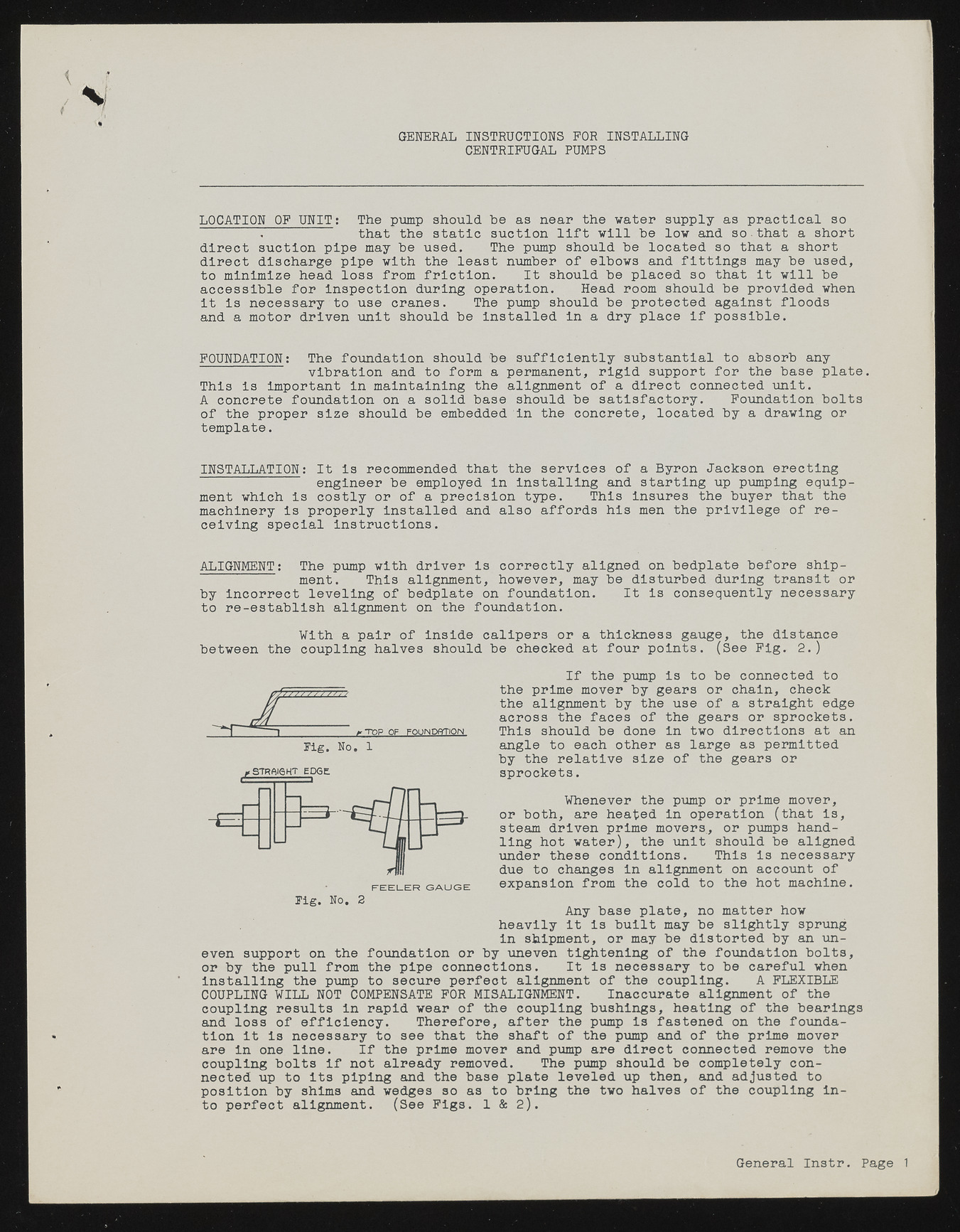
GENERAL INSTRUCTIONS FOR INSTALLING CENTRIFUGAL PUMPS LOCATION OF UNIT: The pump should be as near the water supply as practical so . that the static suction lift will be low and so.that a short direct suction pipe may be used, The pump should be located so that a short direct discharge pipe with the least number of elbows and fittings may be used, to minimize head loss from friction. It should be placed so that it will be accessible for inspection during operation. Head room should be provided when it is necessary to use cranes. The pump should be protected against floods and a motor driven unit should be installed in a dry place if possible. FOUNDATION: The foundation should be sufficiently substantial to absorb any vibration and to form a permanent, rigid support for the base plate. This is important in maintaining the alignment of a direct connected unit. A concrete foundation on a solid base should be satisfactory. Foundation bolts of the proper size should be embedded in the concrete, located by a drawing or template. INSTALLATION: It is recommended that the services of a Byron Jackson erecting engineer be employed in installing and starting up pumping equipment which is costly or of a precision type. This insures the buyer that the machinery is properly installed and also affords his men the privilege of receiving special Instructions. ALIGNMENT: The pump with driver is correctly aligned on bedplate before shipment. This alignment, however, may be disturbed during transit or by incorrect leveling of bedplate on foundation. It Is consequently necessary to re-establish alignment on the foundation. With a pair of inside calipers or a thickness gauge, the distance between the coupling halves should be checked at four points. (See Fig. 2.) If the pump is to be connected to the prime mover by gears or chain, check the alignment by the use of a straight edge across the faces of the gears or sprockets. This should be done in two directions at an angle to each other as large as permitted by the relative size of the gears or sprockets. Whenever the pump or prime mover, or both, are heated in operation (that is, steam driven prime movers, or pumps handling hot water), the unit should be aligned under these conditions. This is necessary due to changes in alignment on account of expansion from the cold to the hot machine. Any base plate, no matter how heavily it is built may be slightly sprung in shipment, or may be distorted by an un-p uneven tightening of the foundation bolts, or by the pull from the pipe connections. It Is necessary to be careful when Installing the pump to secure perfect alignment of the coupling. A FLEXIBLE COUPLING WILL NOT COMPENSATE FOR MISALIGNMENT. Inaccurate alignment of the coupling results in rapid wear of the coupling bushings, heating of the bearings and loss of efficiency. Therefore, after the pump is fastened on the foundation it is necessary to see that the shaft of the pump and of the prime mover are in one line. If the prime mover and pump are direct connected remove the coupling bolts If not already removed. The pump should be completely connected up to its piping and the base plate leveled up then, and adjusted to position by shims and wedges so as to bring the two halves of the coupling Into perfect alignment. (See Figs. 1 & 2). F E E L E R GAUGE Pig. NO. 2 even support on the foundation or by General Instr. Page 1

