
Search the Special Collections and Archives Portal

Search Results

Display    Results Per Page
Displaying results 101 - 110 of 128

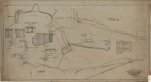
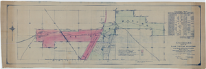
Map showing proposed improvement of Las Vegas Springs, Las Vegas, Nevada, September 21, 1916

Date

1916-09-21

Description

'Exhibit A'. 'Approved Sept. 21, 1916.' 'W.E.J.'"--Lower left corner. 'L-44-50 to 61. T-75 - 17 & 46'--Upper left corner. Includes discharge figures and plans for improvements to springs Scale [ca. 1:240]. 1 in. to 20 feet. -- Scale [ca. 1:2,400]. 1 in. to 200 ft. Vertical scale [ca. 1:48]. 1 in. to 4 feet. -- Scale [ca. 1:4,800]. 1 in. to 100 feet. Library's copy has "Proposed layout" written on it in pencil near lower center and other markings in red. Contents: Detail at springs -- Profile -- Alignment.

Image

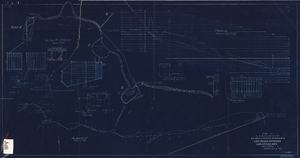
Blueprint showing proposed improvement of Las Vegas Springs, Las Vegas, Nevada, September 21, 1916

Date

1916-09-21

Description

'Exhibit A'. 'Approved Sept. 21, 1916.' '2-N-1719' handwritten in lower right corner. 'W.E.J."--Lower left corner. "L-44 - 50 to 61. T-75 - 17 & 46"--Upper left corner. Includes discharge figures and plans for improvements to springs. Scale [ca. 1:240]. 1 in. to 20 feet. -- Scale [ca. 1:2,400]. 1 in. to 200 ft. Vertical scale [ca. 1:48]. 1 in. to 4 feet. -- Scale [ca. 1:4,800]. 1 in. to 100 feet. 1 map. Contents: Detail at springs -- Profile -- Alignment.

Image

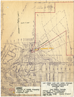
Map showing location of proposed well at Las Vegas, Nevada, August 24, 1948

Date

1948-08-24

Description

'Office of Vice President, Los Angeles, California.' 'Dwg. F-225.' Relief shown by contours. Hand-drawn red line marks portion of ranch property owned by Land Company. Scale [ca. 1:7,200]. 1 in.=600 feet. Blueline.

Image

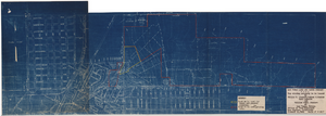
Map showing property to be leased to Willie T. Stewart, Vernon E. Bunker, Earl Leavitt and William Udell Stewart at Las Vegas, Nevada, January 31, 1951

Date

1951-01-31

Description

'Office of Vice President, Los Angeles, California.' Accompanies: William Reinhardt letter to A. E. Stoddard, January 31, 1951 (Box 11 Folder W18-1-12).

Image

Map of Las Vegas Rancho, Lincoln County, Nevada, September 15, 1904

Date

1904-09-15

Description

'Being part of Township 20 S. R.61 E. MT. D. B.&.M, containing 1864.49 acres. Division engineer's office at the front, AMB, September 15th, 1904. A.L. Jones, Division Engineer. Surveyed by W.G. Watson, Assistant Engineer. Dwg. 30296.' Includes traverse table. Shows land owned by the San Pedro, Los Angeles & Salt Lake Railroad, its right of way and the right of way for the Las Vegas & Tonopah Railroad, land owned by the Las Vegas Land & Water Company including Clark's Las Vegas Townsite with the Bucks Addition and the Wardie Addition, and parcels sold from the Las Vegas Land & Water Company land. Scale: [1:9,600]. 1 in. to 800 feet. Library's copies 1 and 4 have land owned by the San Pedro, Los Angeles & Salt Lake Railroad hand-colored in pink and the rest of the Las Vegas Rancho not owned by the Las Vegas Land & Water Company hand-colored in green. Library's copy 2 has buildings of the Stewart Ranch drawn in and labeled in pencil. Library's copy 3 has addition and subtraction problems in pencil on the verso. Library's copy 4 has "Original purchase--1864.49 acres R.R.C. + L.V.L. + W. Co.--In colors." written in pencil on the verso followed by "(1904)" in red pencil. Library's copy 4 also has label on verson made of brown paper with "No 5 Las Vegas Ranch being part township ( 1904)" typed on it.

Image

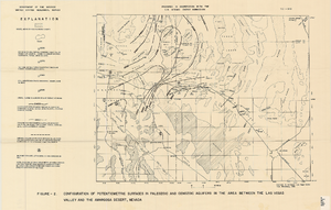
Map showing configuration of potentiometric surfaces in Paleozoic and Cenozoic aquifers in the area between the Las Vegas Valley and the Amargosa Desert, Nevada, 1963

Date

1963

Description

'Department of the Interior, United States Geological Survey. TEI-840.' 'Prepared in cooperation with the U.S. Atomic Energy Commission.' 'Contours in northwest Las Vegas Valley from Malmberg, 1961.' Relief shown by contours. Shows township and range lines. Scale [ca. 1:253,440. 1 in.=aprrox. 4 miles] (W 114°00´--W 115°00´--N 37°00´/N 36°00´). Originally published in A summary of the ground-water hydrology of the area between the Las Vegas Valley and the Amargosa Desert, Nevada : with special reference to the effects of possible new withdrawals of ground water / by Isaac J. Winograd, published by the U.S. Geological Survey in 1963 as number 840 of the Trace elements investigations report.

Image

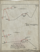
Sketch of plan and profile of present and proposed pipes and tanks and reservoirs at Sloan, Erie and Jean, Nevada, circa 1910s-1920s

Date

1910 to 1929

Description

'No scale. Approved E.M. Jessup, Engr. Maintenance. 7-R-463.'

Image

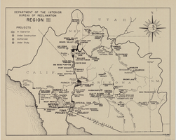
Map of Bureau of Reclamation Region III, August 1, 1945

Date

1945-08-01

Description

31 x 40 cm. "8-1-45. Ness." and "116951" in lower right corner. Shows reclamation projects in operation, under construction, authorized and under study in Arizona, and parts of New Mexico, Utah, Nevada, and California. "Department of the Interior, Bureau of Reclamation" in upper left corner. Original Publisher: Dept. of the Interior, Bureau of Reclamation.

Image

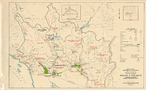
Map showing U.S. Bureau of Reclamation Region 3 projects in Arizona, California, Nevada, New Mexico and Utah, September 1967

Date

1967-09

Description

'United States, Department of the Interior, Stewart L. Udall, Secretary. Bureau of Reclamation, Floyd E. Dominy, Commissioner.' 'Map. No. X-300-738. September 1967.' Scale [ca. 1:1,774,080] (W 119°--W 108°/N 39°--N 32°). Relief shown pictorially. Shows completed, under construction and proposed dams and reservoirs, canals, and aqueducts, power plants, pumping plants, substations, transmission lines, tunnels and siphons. Also shows non-Bureau of Reclamation dams, reservoirs, tunnels, pipelines and irrigated lands. Includes inset map of location of Region 3 and key map of drainage basins. Bureau of Reclamation, [Region 3?].

Image

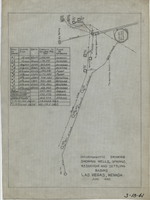
Diagrammatic drawing showing wells, springs, reservoir and settling basins, Las Vegas, Nevada, June 1942

Date

1942-06

Description

Hand-drawn in pencil on tracing cloth. "June 1942." Also shows pipelines and power lines. Includes a hand-written table showing the number of the well or spring, casing size, depth, capacity in gallons per day, and whether it is pump or artesian. "3-18-41"--Written in black grease pencil in lower right corner of map.

Text