Search Results
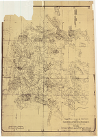
Map of approved mineral surveys in the Goldfield Mining District, Esmeralda and Nye Counties, Nevada, 1911
Date
1911
Description
'Compiled from records of the U.S. Surveyor General and other authentic sources by Davis and Byler, Mining Engineers, Goldfield, Nevada. Copyright 1908 by Davis and Byler. 1911.' Scale [ca. 1:9,600]. 1 in. to 800 feet. (W 117°14'--W 117°09'/N 37°46'--N 37°41'). Blueline print. Includes township and range grid. Library's copy has upper-left corner torn off and has circles drawn around and diagonal lines drawn on certain claims.
Image
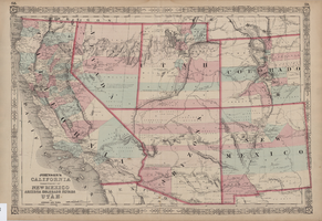
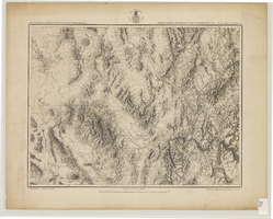
Map of California, territories of New Mexico, Arizona, Colorado, Nevada and Utah, circa 1863
Date
1861 to 1865
Description
40 x 62 cm. Relief shown by hachures and spot heights. Prime meridians: Greenwich and Washington. "Historical and statistical view of the United States, 1860"--Verso. Atlas page numbers at top: 58-59. Arizona became a territory in 1863, and Nevada became a state on October 31, 1864, so this map was either published in 1863 or in 1864 before the end of October. Original publisher: Johnson and Ward.
Image
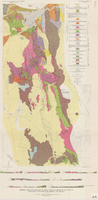
Geologic map and sections of area along Colorado River between Lake Mead and Davis Dam, Arizona and Nevada, 1963
Date
1963
Description
At top of map: 'United States, Department of Interior, Geological Survey. Professional Paper 374-E, plate 1.' In lower right corner of map: 'Geology mapped by C.R. Longwell.' Relief shown by contours. Includes seven colored cross-sections. Scale 1:125,000 (W 114°50´--W 114°20´/N 36°10´--N 35°10´). Series: Shorter contributions to general geology. Professional paper (Geological Survey (U.S.))374-E. Originally published as plate 1 in: Reconnaissance geology between Lake Mead and Davis Dam, Arizona-Nevada / by Chester R. Longwell, published by the U.S. Government Printing Office in 1963 in the series Shorter contributions to general geology and as Geological Survey professional paper 374-E.
Image
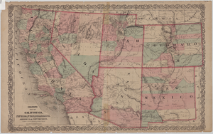
Map of California, Nevada, Utah, Colorado, Arizona & New Mexico, circa 1867
Date
1865 to 1869
Description
39 x 62 cm. Relief shown by hachures and spot heights. Prime meridian: Greenwich and Washington. Hand colored. Shows natural features, populated places, routes of mail steamships, routes of explorers, locations of Indian tribes, railroad routes, and proposed railroad routes. In top margin: No. 80-81. On verso: New Mexico, Arizona, Colorado, Idaho, Dakota (statistics and other information) and The state of California (statistics and other information). Original publisher: G.W. and C.B. Colton.
Image
Map showing parts of eastern and southeastern Nevada and southwestern Utah, circa 1873
Date
1869
1872 to 1873
Archival Collection
Description
Scale 1:506,880. 1 in. to 8 miles (W 117°30--W 114°45/N 37°20--N 40°00). Relief shown by hachures and spot heights. At top left: 'Explorations & surveys west of the one-hundredth meridian.' At top right: 'Parts of Eastern & Southeastern Nevada & Southwestern Utah. Atlas sheet number 66.' At bottom left: 'Expeditions of 1869, 1872 & 1873.' At bottom right: ' 1st Lieut. Geo. M. Wheeler, Corps of Engineers, com'd'g.' Seal of the War Department, Corps of Engineers, U.S. Army at top center of map. Originally published as part of the geological atlas which is an appendix to the Survey's Report upon United States geographical surveys west of the one hundredth meridian, published in 1876?
Image
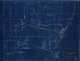
Map showing profile of 24-inch cast iron water pipeline for Las Vegas, Nevada, May 20, 1930
Date
1930-05-20
Archival Collection
Description
'As constructed. Drawing W.O. - 8577. Office of Chief Engineer, Los Angeles. Drawing No. 41092.' 'Scale for details 1"=10'. 5-20-1930. P.F.D.' 'Scale 1"=100'.' 'Profile of new 24" CI pipe. Scale 1"=600'. Ver. 1"=20'.' Blueprint. Map of the water pipes for Las Vegas. Includes the buildings in the railroad yard, a detailed map of a section of the pipe, a profile of the 24 inch C.I. pipe, and a map of the point of diversion. Date of detailed map is 5-20-1930. Library's copy has hand-written additions in color. Los Angeles & Salt Lake Railroad Co., Office of Chief Engineer,
Image
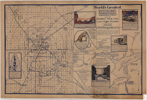
Map of Boulder Dam area and Las Vegas, Nevada, October 7, 1930
Date
1930-10-07
Description
'F.V. Owen, publisher ... Los Angeles, California. Topography by C.H. Fenner, C.E. Decorations by L.J. Bergère. Gov't. data, H.A. Shamberger, C.E. Copyright, 1930, by F.V. Owen.' At bottom right of map: 'Dated Oct. 7th, 1930.' Relief shown by contours and spot heights. Contour lines are 100 feet. Incudes six hand-colored illustrations showing local points of interest. Includes information on Hoover Dam, and chart of mileages from Las Vegas. Scale [ca. 1:63,360]. 1 inch to 1 mile
Text
Map showing proposed new 12" well and pipe line changes at Water Springs, Las Vegas, Nevada, circa 1920
Date
1916 to 1925
Archival Collection
Description
In lower right corner: '6-W-74.' Scale: 1" = 500'.
Image
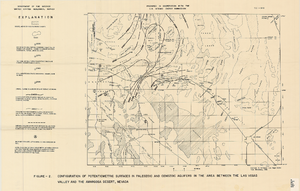
Map showing configuration of potentiometric surfaces in Paleozoic and Cenozoic aquifers in the area between the Las Vegas Valley and the Amargosa Desert, Nevada, 1963
Date
1963
Description
'Department of the Interior, United States Geological Survey. TEI-840.' 'Prepared in cooperation with the U.S. Atomic Energy Commission.' 'Contours in northwest Las Vegas Valley from Malmberg, 1961.' Relief shown by contours. Shows township and range lines. Scale [ca. 1:253,440. 1 in.=aprrox. 4 miles] (W 114°00´--W 115°00´--N 37°00´/N 36°00´). Originally published in A summary of the ground-water hydrology of the area between the Las Vegas Valley and the Amargosa Desert, Nevada : with special reference to the effects of possible new withdrawals of ground water / by Isaac J. Winograd, published by the U.S. Geological Survey in 1963 as number 840 of the Trace elements investigations report.
Image
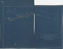
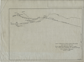
Blueprint map showing proposed new 12" well and pipe line changes at water springs, Las Vegas, Nevada, circa 1920
Date
1916 to 1925
Archival Collection
Description
Stamped : 'Approved (Signed) A. Maguire, Assistant Chief Engineer.' In lower right corner: '6-W-74.' Some annotations written over in yellow; black dotted line added between forebay and final spring in the northwest. Scale [ca. 1:6,000] 1 in.=500 feet
Image