Search Results
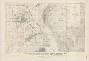
Map of part of Las Vegas Valley, Nevada, showing approximate area of phreatophytes before ground-water development
Date
1965
Description
Genre/Form: Thematic maps. Scale 1:62,500 (W 115°15´--W 114°45´/N 36°15´--N 36°00´). 1 map : col. ; 44 x 72 cm. Series: Water-supply paper (Washington, D.C.) ; 1780. Relief shown by contours. Originally published as plate 10 of Available water supply of the Las Vegas ground-water basin, Nevada, by Glenn T. Malmberg, published by the Geological Survey in 1965 as its Water-supply paper 1780. Includes township and range lines. Interior, Geological Survey
Image
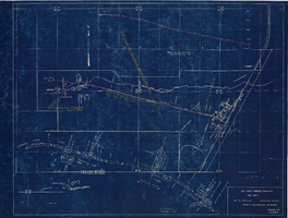
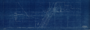
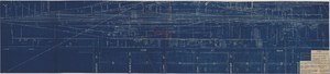
Map showing profile of 24-inch cast iron water pipeline for Las Vegas, Nevada, May 20, 1930
Date
1930-05-20
Archival Collection
Description
'As constructed. Drawing W.O. - 8577. Office of Chief Engineer, Los Angeles. Drawing No. 41092.' 'Scale for details 1"=10'. 5-20-1930. P.F.D.' 'Scale 1"=100'.' 'Profile of new 24" CI pipe. Scale 1"=600'. Ver. 1"=20'.' Blueprint. Map of the water pipes for Las Vegas. Includes the buildings in the railroad yard, a detailed map of a section of the pipe, a profile of the 24 inch C.I. pipe, and a map of the point of diversion. Date of detailed map is 5-20-1930. Library's copy has hand-written additions in color. Los Angeles & Salt Lake Railroad Co., Office of Chief Engineer,
Image
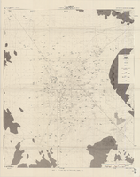
Map showing ground-water chemistry and hydrochemical facies, Nevada Test Site and vicinity, southern Nevada, 1965
Date
1965
Description
'United States Department of the Interior, Geological Survey. Professional paper 712-C, plate 3.' 'Prepared on behalf of the Atomic Energy Commission.' 'Base from U.S. Geological Survey Caliente, Death Valley, Goldfield, and Las Vegas, 1954.' 'Hydrochemistry by I. J. Winograd, 1965.' 'Interior--Geological Survey, Reston, Virginia--1975.' Relief shown by contours. Contour interval 200 feet. Shows township and range lines. Scale 1:250,000 (W 117°--W 115°/N 38°--N 36°). Series: Professional paper (Geological Survey (U.S.))712-C. Issued as plate 3 from U.S. Geological Survey professional paper 712-C, Hydrogeologic and hydrochemical framework, south-central Great Basin, Nevada-California, with special reference to the Nevada Test Site, by I.J. Winograd, and William Thordarson, published in 1975 by the U.S. Geological Survey.
Image
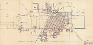
Map showing facilities of the Las Vegas Land and Water Co. completed, under construction and commenced after September 1, 1952
Date
1953-04-29
Description
'Exhibit D. Facilities of Water Company completed as of September 1, 1952. Facilities of Water Company under construction as of September 1, 1952. Facilities of Water Company which were commenced after September 1, 1952, and prior to March 1, 1954. April 29, 1953. I-67.'
Image
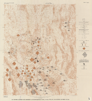
Map of the Nevada Test Site and vicinity showing principal rock types and chemistry of ground water, 1964
Date
1964
Description
'Compiled by S.L. Schoff and J.E. Moore.' 'Geology generalized from geologic maps of the Nevada Test Site by Special Projects Branch, U.S. Geological Survey; of Lincoln County by Tschanz and Pampeyan (1961); and of Clark County by Bowyer, Pampeyan, and Longwell (1958).' United States Department of the Interior, Geological Survey. Prepared in cooperation with the U.S. Atomic Energy Commission.' 'TEI-838.' Scale 1:125,000 (W 116°00´--W 116°15´/N 37°15´--N 36°30´). Originally published as figure 1 in Chemistry and movement of ground water, Nevada Test Site / by Stuart L. Schoff and John E. Moore, published by the Geological Survey in 1964 as number 838 of the Trace elements investigations report.
Image
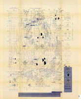
Topographic map of Las Vegas Rancho, showing location of wells and water lines, Las Vegas, Nev., May 1, 1940
Date
1940-05-01
Description
'May 1, 1940.' 'F-225.' Relief shown by contours. Scale [ca. 1:7,200] 1 in.=600 feet. Blueprint.
Image
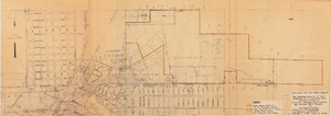
Map showing location of leased properties proposed to be sold to the Las Vegas Land and Water Company, October 2, 1952
Date
1952-10-02
Archival Collection
Description
'October 2, 1952.' Relief shown by contours. Hand-drawn lines mark land leased to these people, land proposed to be withdrawn from lease, and easement for a sewer. Scale [ca. 1:7,200]. 1 in.=600 feet. Blueline.
Image
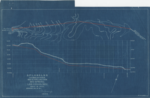
Blueprint map showing proposed water pipeline from Big Spring to Las Vegas, Nevada, January 24, 1911
Date
1911-01-24
Archival Collection
Description
'S.P.L.A.&S.L.R.R. Los Angeles Division. Map of pipe line from Big Spring. Las Vegas, Nev. Approved: Jan. 24, 1911. E.M. Jessup, E.M. of W.' In lower right corner: '4-U-323.' Scale [ca. 1:2,400] 1 in.=200 feet. Relief shown by contours. North is to upper right.
Image
Map showing location of proposed water lines serving Industrial Tract No. 1, Las Vegas Nevada, March 21, 1931
Date
1931-03-21
Archival Collection
Description
'Office of Ind'l. Engineer, Los Angeles, California.' 'Dwg. No. 568.' Scale: 1" = 100'.
Image
Map of well locations, Las Vegas Valley, Nevada, 1975
Date
1976
Description
'Cartography by Marj Thielke.' 'Prepared in cooperation with the State of Nevada, Department of Conservation and Natural Resources, Division of Water Resources.' Relief shown by contours. Shows township and range lines. Originally published as Plate 1 in Water-level changes associated with ground-water development in Las Vegas Valley, Nevada, 1971-75 : fourth progress report--summary of data / by James R. Harrill, published in 1976 by the Department of Conservation and Natural Resources, Division of Water Resources, as volume 22 of Water resources-information series report. Scale [ca. 1:69,696. 1 in.=approx. 1.1 miles] (W 115°20´--W 115°00´/N 36°20´--N 36°00´).
Image