Copyright & Fair-use Agreement
UNLV Special Collections provides copies of materials to facilitate private study, scholarship, or research. Material not in the public domain may be used according to fair use of copyrighted materials as defined by copyright law. Please cite us.
Please note that UNLV may not own the copyright to these materials and cannot provide permission to publish or distribute materials when UNLV is not the copyright holder. The user is solely responsible for determining the copyright status of materials and obtaining permission to use material from the copyright holder and for determining whether any permissions relating to any other rights are necessary for the intended use, and for obtaining all required permissions beyond that allowed by fair use.
Read more about our reproduction and use policy.
I agree.Information
Digital ID
Permalink
Details
Member of
More Info
Rights
Digital Provenance
Publisher
Transcription
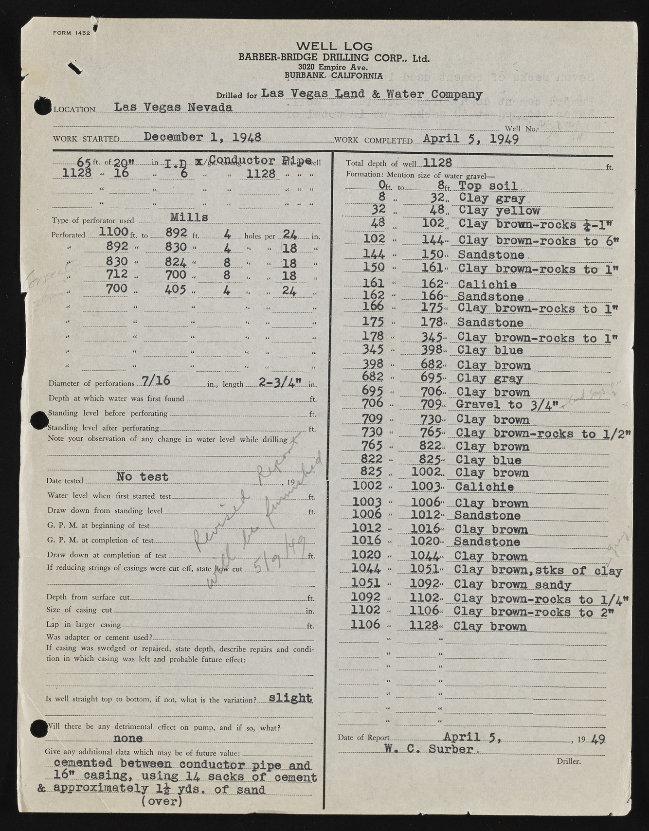
FO RM 1432 I LOCATION.. W E L L LO G BARBER-BRIDGE DRILLING CORP.. Ltd. 3020 Empire Ave. BURBANK, CALIFORNIA Drilled f o r . L a s . . V e g a s . . . L a n d W ater Company Las Vegas Nevada 1 WORK STARTED- Decembe r 1, 1948 65 fr ifSfi*— a 1128 « 16 Type of perforator used M i l ls i 1100 ft. to ... 892 f, . 4 892 1 830 ?< 4 .. 18 “ . 830 1 i 824 “ 8 “ •< 18 - 712 ., 7 0 0 .. 8 .. .. 18 I 700 .. 405 - 4 .. .. 24 .. Diameter of perforations 7/16 Depth at which water was first found..... (Standing level before perforating _____._ Standing level after perforating_________ -in., length. Note your observation of any change in water level while drilling. ----------^ [) \ A Date tested... __ — ^ . — 19 iJ Water level when first started test____ & L ft. Draw down from standing level______ . y _ v _ i j . ft. G. P. M. at beginning of test > r M \ G. P. M. at completion of test______ U | Draw down at comoletion of test 1 T ' .ft. If reducing strings of casings were cut off. state h d w cut / \ v \ .. l r Depth from surface cut. .__ ____ ft. Size of casing cut__ _____ _____ Lap in larger casing............... ft Was adapter or cement used? If casing was swedged or repaired, state depth, describe tion in which casing was left and probable future effect: repairs and condi- Is well straight top to bottom, if not. what is the variation? S l i g h t ?Vill there be any detrimental effect on pump, " .................. none___ _______________ and if so, what? Give any additional data which may be of future value:________ ________ _ cementedbetweeii conduotp-r p i pa grid 16” . casing, using 14 sacks o f cement &...approxim ately 1%- yds , o f sand ( over) weii mm WORK COMPLETED A p r i l 5,.. 1949 K/irf.osid|A.ctpr.„ lip^eii .. 1128 ....... Total depth of well. .1128 Formation: Mention size of water gravel— .Oft. to 8ft T op s o i l 8 52 150 161 162 166 175 17.8 682 695 706 7P9 -730 765 822 825 1002 ..1QQ3 .1006 1012 1016 1020 1044 1102 1106 32., C lay gray 48.. C lay y e llo w 102„ Clay brown-rocks £-1™ 144- C lay b ro w n ~ro ck st o 6 w 150“ Sand ston e. 161“ Clay brown-rocka to j " 162“ C a lie h ie ______________ _ 1 6 6 ...jSandstone . ________ C lay brow n-rooks to 1” 178“ Sandstone .145- C lay brown-rocks to 1" C lay b lu e ___~ 682- C lay brown 695* C lay gray 706“ C lay brown 709“ Grave l to 374" C lay brown __765“ C lay brown-rocks to 1/2" 822“ C lay brown__ 825“ C lay b lue_________ 1002.. Clay brown 1003“ C a lic h ie _10.Q.6“ ... Clay, brown______________ 1012“ -Sandstone._______________ 1016“ C lay brown__________ 1020“ Sandstone Clay brown 1051 C lay brownrstk s o f n ifty 1092“ C lay brown sandy______ 1102- C lay brown- rocks t.n 1/4" 1106“ Clay brown-rocks to 2" 1128- Clay brown Date of Report_______ ____ A p r il-5 ,.-----------------. 19-49 S u r b e r,._______ Driller.

