Copyright & Fair-use Agreement
UNLV Special Collections provides copies of materials to facilitate private study, scholarship, or research. Material not in the public domain may be used according to fair use of copyrighted materials as defined by copyright law. Please cite us.
Please note that UNLV may not own the copyright to these materials and cannot provide permission to publish or distribute materials when UNLV is not the copyright holder. The user is solely responsible for determining the copyright status of materials and obtaining permission to use material from the copyright holder and for determining whether any permissions relating to any other rights are necessary for the intended use, and for obtaining all required permissions beyond that allowed by fair use.
Read more about our reproduction and use policy.
I agree.Information
Digital ID
Permalink
Details
More Info
Rights
Digital Provenance
Publisher
Transcription
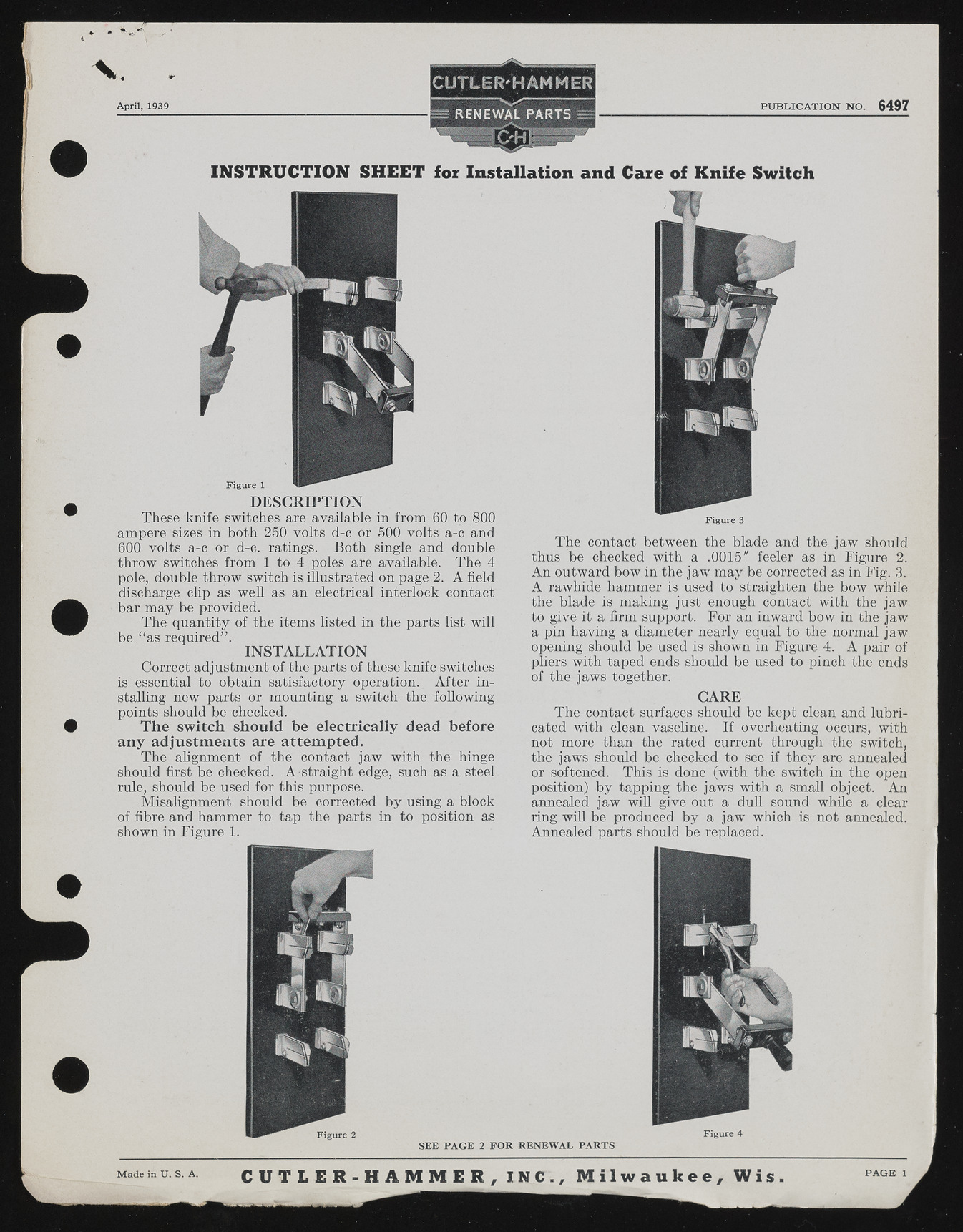
V April, 1939 PUBLICATION NO. 6497 INSTRUCTION SHEET lor Installation and Care of Knife Switch DESCRIPTION These knife switches are available in from 60 to 800 ampere sizes in both 250 volts d-c or 500 volts a-c and 600 volts a-c or d-c. ratings. Both single and double throw switches from 1 to 4 poles are available. The 4 pole, double throw switch is illustrated on page 2. A field discharge clip as well as an electrical interlock contact bar may be provided. The quantity of the items listed in the parts list will be “ as required” . INSTALLATION Correct adjustment of the parts of these knife switches is essential to obtain satisfactory operation. After installing new parts or mounting a switch the following points should be checked. The switch should be electrically dead before any adjustments are attempted. The alignment of the contact jaw with the hinge should first be checked. A straight edge, such as a steel rule, should be used for this purpose. Misalignment should be corrected by using a block of fibre and hammer to tap the parts in to position as shown in Figure 1. Figure 3 The contact between the blade and the jaw should thus be checked with a .0015" feeler as in Figure 2. An outward bow in the jaw may be corrected as in Fig. 3. A rawhide hammer is used to straighten the bow while the blade is making just enough contact with the jaw to give it a firm support. For an inward bow in the jaw a pin having a diameter nearly equal to the normal jaw opening should be used is shown in Figure 4. A pair of pliers with taped ends should be used to pinch the ends of the jaws together. CARE The contact surfaces should be kept clean and lubricated with clean vaseline. If overheating occurs, with not more than the rated current through the switch, the jaws should be checked to see if they are annealed or softened. This is done (with the switch in the open position) by tapping the jaws with a small object. An annealed jaw will give out a dull sound while a clear ring will be produced by a jaw which is not annealed. Annealed parts should be replaced. Figure 2 S E E P A G E 2 F O R R E N E W A L P A R T S Figure 4 Made in U. S. A. C U T L E R - H A M M E R , I N C . , M i l w a u k e e , Wi s PAGE 1

