Copyright & Fair-use Agreement
UNLV Special Collections provides copies of materials to facilitate private study, scholarship, or research. Material not in the public domain may be used according to fair use of copyrighted materials as defined by copyright law. Please cite us.
Please note that UNLV may not own the copyright to these materials and cannot provide permission to publish or distribute materials when UNLV is not the copyright holder. The user is solely responsible for determining the copyright status of materials and obtaining permission to use material from the copyright holder and for determining whether any permissions relating to any other rights are necessary for the intended use, and for obtaining all required permissions beyond that allowed by fair use.
Read more about our reproduction and use policy.
I agree.Information
Digital ID
Permalink
Details
More Info
Rights
Digital Provenance
Publisher
Transcription
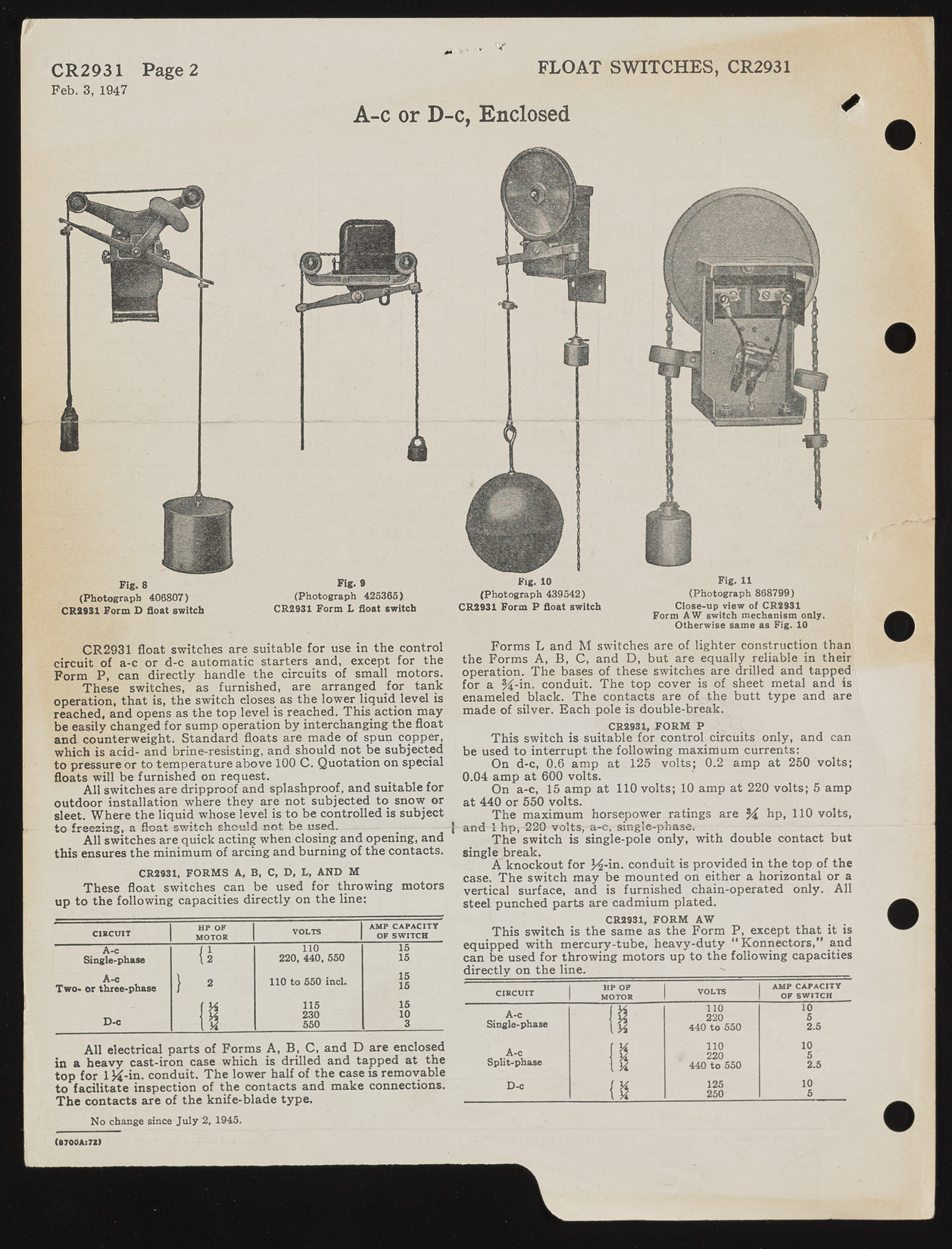
CR2931 Page 2 Feb. 3, 1947 '•4* FLOAT SWITCHES, CR2931 A-c or D-c, Enclosed ? Fig. 9 (Photograph 425365). CR2931 Form L float switch Fig. 8 (Photograph 406807) CR8931 Form D float switch CR2931 float switches are suitable for use in the control circuit of a-c or d-c automatic starters and, except for the Form P, can directly handle the circuits of small motors. These switches, as furnished, are arranged for tank operation, that is, the switch closes as the lower liquid level is reached, and opens as the top level is reached. This_ action may be easily changed for sump operation by interchanging the float and counterweight. Standard floats are made of spun copper, which is acid- and brine-resisting, and should not_be subjected to pressure or to temperature above 100 C. Quotation on special floats will be furnished on request. All switches are dripproof and splashproof, and suitable for outdoor installation where they are not subjected to snow or sleet. Where the liquid whose level is to be controlled is subject to freezing, a float switch should not be .used. All switches are quick acting when closing and opening, and this ensures the minimum of arcing and burning of the contacts. CR2931, FO R M S A, B , C, D, L, AND M These float switches can be used for throwing motors up to the following capacities directly on the line: C IR C U IT HP OF MOTOR VOLTS AMP CAPACITY OF SW ITCH / I 110 15 Single-phase \2 220, 440, 550 15 A-c Two- or three-phase } 2 110 to 550 incl. 15 15 115 15 D-c 1 12 230 1 0 f X 550 3 All electrical parts of Forms A, B , C, and D are enclosed in a heavy cast-iron case which is drilled and tapped at the top for 1 K -in. conduit. The lower half of the case is removable to facilitate inspection of the contacts and make connections. The contacts are of the knife-blade type. No change since Ju ly 2, 1945. Fig. 10 (Photograph 439542) CR2931 Form P float switch Fig. 11 (Photograph 868799) Close-up view of CR2931 Form AW switch mechanism only. Otherwise same as Fig. 10 Forms L and M switches are of lighter construction than the Forms A, B , C, and D, but are equally reliable in their operation. The bases of these switches are drilled and tapped for a %-in. conduit. The top cover is of sheet metal and is enameled black. The contacts are of the butt type and are made of silver. Each pole is double-break. CR2931, FO R M P This switch is suitable for control circuits only, and can be used to interrupt the following maximum currents: On d-c, 0.6 amp at 125 volts; 0.2 amp at 250 volts; 0.04 amp at 600 volts. On a-c, 15 amp at 110 volts; 10 amp at 220 volts; 5 amp at 440 or 550 volts. The maximum horsepower ratings are % hp, 110 volts, | and 1 hp, 220 volts, a-e, single-phase. The switch is single-pole only, with double contact but single break. A knockout for H-m- conduit is provided in the top of the case. The switch may be mounted on either a horizontal or a vertical surface, and is furnished chain-operated only. All steel punched parts are cadmium plated. CR2931, FO RM AW This switch is the same as the Form P, except that it is equipped with mercury-tube, heavy-duty " K onnectors," and can be used for throwing motors up to the following capacities directly on the line._____________________-- VOLTS AMP CAPACITY C IRC U IT MOTOR OF SW ITCH A-C 1 110 10 Single-phase Vi 220 5 \ % 440 to 550 2.5 r u 110 10 A-c Split-phase H \ y*. 220 440 to 550 5 2.5 D-c 1 x 125 10 \ K 250 5 ( 9 7 0 0 A : 7 2 )

